Communication between various 802.15.4 sensor motes : iMote2
(CC2420, .NET & TinyOS), TelosB & MicaZ (CC2420,
TinyOS), WaspMote (Digi XBee, Libelium) and Arduino (Mega
2560+XBee shield+Digi XBee)
last update: June 14th, 2013.
Introduction
For those who have several sensor platforms communications,
interoperability between various sensor boards is an issue. Commonly
found sensors boards a few years ago were Mica2, MicaZ
and TelosB
then came the iMote2
which is much more powerful than the previous motes (you can see this page
from the TinyOS project or this one
from U. Washington.). Most of these boards run under the TinyOS
system. Their radio module is a TI CC2420 which is
also quite powerfull and flexible. There are lots of documention on
the web. AdvanticSys
also propose TelosB-based sensor motes with many extension boards.
Recenty, Waspmote board from Libelium became quite attractive
because of their ease of programming based on the open-source
Arduino IDE. These WaspMote motes have been deployed in large-scale
in the Santander city (Spain, see
deployment map) as part of the SmartSantander EU project.
Arduino hardware is also very
well-known from the electronic community and quite interesting
sensor boards could be realized on an Arduino basis. Both Waspmote
and Arduino boards use the Digi
XBee modules for 802.15.4 connectivity. Both CC2420 and Digi
XBee are 802.15.4 compliant therefore it is possible to make them
communicate in order to build sensor networks with a mixture of
hardware platforms. Although the CC2420 is much more flexible than
the XBee because many parameters can be tuned, the XBee module is
very versatile and easy to use. Also, an XBee module has an IEEE
64-bit address while the CC2420 still do not have such feature, at
least to the best of my knowledge.
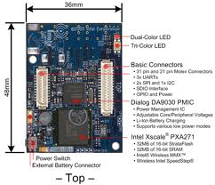

Figure 1: from left to right: iMote2, WaspMote, TelosB,
MicaZ
The iMote2 from Crossbow came either with the .NET firmware or the
TinyOS support. The development environment shipped with the .NET
version is based on Windows with Visual Studio 5 and the Micro .NET
framework. The librairies are quite complete and also support
limited TinyOS compatibility. If you have the TinyOS version of the
iMote2, the information provided in this page also apply to you.
With TinyOS, you can either use the default ActiveMessage layer or a
fully 802.15.4 compliant protocol stack (tkn154, see tinyos-2.x/apps/tests/tkn154, only on
MicaZ and TelosB, not iMote2. For iMote2, use Ieee154 component instead with
limitation on using only 16-bit addresses). Arduino proposes an
open-source IDE based on Processing which offer a very simple way to
rapidly develop prototypes. Waspmote boards from Libelium are
shipped with a custom version of the Arduino IDE. As iMote2, TelosB,
MicaZ, Waspmote and Arduino boards are quite representative, this
document presents our preliminary tests and solutions for making
them able to communicate.
Connecting with USB
In most of the operations described in this page, the various sensor
boards will need to be connected to a computer (for uploading
program, for reading the serial data,...). If you are using MAC OS X, you will probably have
no problem as the USB port will be detected quite easily by the
Libelium or Arduino IDE. Same thing if you are using the serial tool
Zterm on MAC OS X. If you are
using Linux, the new versions do have built-in FTDI
support so you should not having problem. However, sometime the name
of the serial port can change. For instance, Libelium Waspmote are
usually accessible under ttyUSB0. The Arduino board usually are
accessible under ttyACM0. For the iMote2, you may need to have the
debug board and use the USB port of the debug board to connect to
the computer. These debug boards offer 2 FTDI ports, usually ttyUSB0
and ttyUSB1. In all cases, you can use the dmesg
program to determine the name of the port under Linux: plug the USB
cable and type dmesg to see the name under which
the system has detected your USB device. I'm not using Windows platform, except for
programming the .NET iMote2 so check on the web fo further
information.
iMote2 under .NET: communicating with an XBee gateway
First of all, in order for the 2 radios to be able to communicate,
you have to ensure that they are both in the same PAN ID and in the
same channel. See this page for how to set
this on the XBee. Here, let's assume that both are on PAN ID 0x1234
and channel 0x0D.
In addition to these basic settings, on the XBee, you have to set
the Mac mode to either 1 or 2, but 2 is better with acknowledgment.
The Libelium come with a Mac mode of 0 by default, which
inserts/removes transparently 2 additional bytes in the payload
portion of the standard 802.15.4 frame structure. Also, I prefer to
use 64-bit addressing instead of the 16-bit because the latter is
independant from the hardware MAC address and is therefore more
difficult to debug. Finally, the right settings for the XBee should
be, using AT command syntax:
atid1234
atchd
atmm2
atmyffff
atwr
It is also advised to disable encryption and to use API mode 2 with escaped
characters:
atee0
atap2
atwr
In a first step, we can use the Libelium gateway (a USB-serial
converter for the XBee module) to sniff all packets from an iMote2.
The gateway will be inserted into a PC under Windows, MACOSX or
Linux running any serial tool such as HyperTerminal, Zterm or
minicom respectively. The Libelium XBee serial connection
configuration is:
- baud rate : 38400
- flow control: none
- data bit: 8
- parity: none
- stop bits: 1
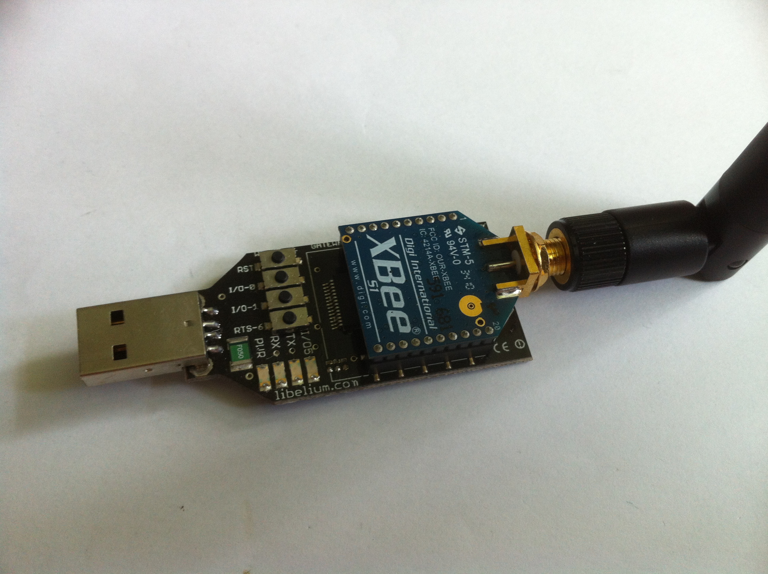
Figure 2. XBee USB-Serial gateway from Libelium
With the gateway, there is no software needed on the Libelium side:
an iMote2 will be used to broadcast 802.15.4 packets that will be
received by the Libelium XBee gateway and send on the serial line of
the gateway. The iMote2 runs a simple C# test program that send
'AAAAABBBBB' as the payload. Here is the code of this simple
program:
using
Crossbow.lib.utils;
using
Crossbow.radio.cc2420;
using
Crossbow.platform.imote2;
namespace
Crossbow.app
{
public
class myTest
{
static
Leds m_Leds = new Leds();
public
static void Main()
{
const
ushort _rfChannel = (ushort)RadioChannel.Ch13; // channel 13
const
ushort _rfPower = (ushort)RadioPower.M10DBM; // -10dbm
SerialDump.print("App
[myTest]: Started."); // Print the applicaiton identifier
Radio
radio = new Radio(_rfChannel, _rfPower, 0x1234, 0x5678);
byte[]
packet = new byte[10];
m_Leds.setRGB(LedColor.YELLOW);
for
(; ; )
{
try
{
for
(int i = 0; i < 5; i++)
packet[i]
= (byte)'A';
for
(int i = 5; i < 10; i++)
packet[i]
= (byte)'B';
//
payload is AAAAABBBBB
m_Leds.setRGB(LedColor.BLUE);
System.Threading.Thread.Sleep(500);
radio.Send((ushort)0xFFFF,
(ushort)0xFFFF, packet);
m_Leds.setRGB(LedColor.YELLOW);
System.Threading.Thread.Sleep(2000);
}
catch
(System.Exception ex)
{
SerialDump.print("App
[myTest]: " + ex.Message);
}
}
}
}
}
The line Radio radio = new Radio(_rfChannel,
_rfPower, 0x1234, 0x5678); defines a radio
configured in PAN ID 0x1234, channel 0x0D (13 in decimal) with a
16-bit address of 0x5678. Actually, you can put anything you want
for the 16-bit address here since we are going to broadcast the
packet with the line radio.Send((ushort)0xFFFF,
(ushort)0xFFFF, packet);.
With a serial tool such as minicom you will get the raw data from
the XBee module which should look like:
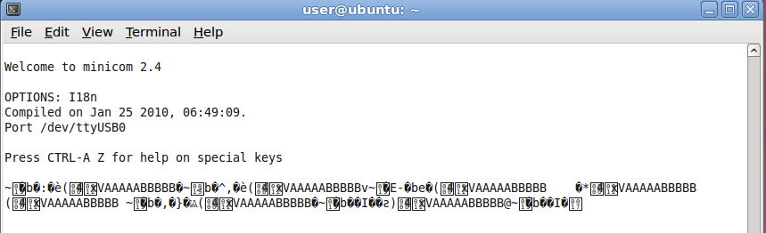
Figure 3.
The hex form is something like:
7e 00 19
80 62 af 2c d1 7d c3 1a a8 3f 06 34 12 78 56 41 41 41 41 41 42 42
42 42 42 87
which could be decoded as follows with the API frame structure used
by the XBee for XBee->Application communications.
7E: frame start delimiter
00: Length msb
19: Length lsb
80: RX packet (64bits)
Source address : 62 af 2c d1 7d c3 1a a8
RSSI : 3f
Option : 06 Address broadcast PAN broadcast
Data : 34 12 78 56 41 41 41 41 41 42 42 42 42 42
Checksum: 87
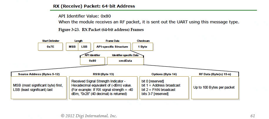
Figure 4.
Actually, the 64-bit address field is varying so this information
seems not to be reliable. The length is 0x0019 so 25 in decimal.
This is correct as it counts from the 0x80 to the last data byte
0x42. According to the API frame, we can see that the PAN ID 0x1234
and the 16-bit address of 0x5678 becomes part of the payload. If you
look at the .NET implementation (RadioCC2420.cs) then you will see
that the BuildFrame() function, prior to sending the frame, does
insert the source PAN ID and the source short address in the
payload. Here, on the XBee, the important thing is that we actually
received something and that the data part 'AAAAABBBBB' can be
identified somewhere in the frame.
iMote2 under .NET: communicating with a Waspmote
The next step is to realize a communication between an iMote2 and a
Waspmote (with the XBee module). For this purpose, the program on
the iMote2 side is the same but we need a program on the Waspmote to
realize the function of the USB-serial gateway. In addition, we do
not want the raw data but only the real data part, i.e.
'AAAAABBBBB'.
It is not possible to use the traditional Libelium API to receive
the packets from the iMote since the Libelium API performs a lot of
additional steps that rely on additional headers specific to the
Libelium API. We recall here the traditional Libelium API for
receiving a packet:
if(
XBee.available() )
{
xbee802.treatData();
if(
!xbee802.error_RX )
{
//
Writing the parameters of the packet received
while(xbee802.pos>0)
{
for(int
f=0;f<xbee802.packet_finished[xbee802.pos-1]->data_length;f++)
{
XBee.print(xbee802.packet_finished[xbee802.pos-1]->data[f],BYTE);
}
}
}
}
In our case, we will directly use the XBee.read()function to get
all the raw data received by the XBee module. Actually, xbee802.treatData()
calls xbee802.parseMessage()
which exactely does the same XBee.read()calls. Our code is
largely based on the code found in xbee802.parseMessage()but
in a much simpler version that does not take into account multiple
fragments. Here is a typical statement to be inserted in a
loop to get all the data from the XBee:
if
(XBee.available()) {
memory[i]=XBee.read();
i++;
}
You will get in memory all the raw data that you can process later
on. The whole
code can be found here but I advised you to have a look at it
later. The next step is to enable the reception of both iMote2 data
and data from other Waspmote that are using the Libelium API. We
will describe this step in the next section and will provide more
information on the code to explain what we did.
Receiving both iMote2 data and Waspmote data on a Waspmote
The iMote2 program is the same: it sends 'AAAAABBBBB' as the
payload. We still have our first Waspmote (noted WA) with the
previous receiving code. We use a second Waspmote (noted WB) with
the WaspXBee802_2_sending_receiving
program shipped by the IDE practically unchanged. The slightly
modified code can be found here.
In order to be able to receive from both an iMote and a Waspmote
using the Libelium API, we have to find a way to determine from the
raw data its origin. We did this this way, it may be not the best
way, a Waspmote is required to
- use a predefined application ID (for instance 0x52 as used in
the Libelium example)
- use a source ID string set to "WASP"
Here is the code for sending a packet with the Libelium API that
satisfies these 2 constraints:
//
Set params to send
paq_sent=(packetXBee*) calloc(1,sizeof(packetXBee));
paq_sent->mode=BROADCAST;
paq_sent->MY_known=0;
paq_sent->packetID=0x52;
paq_sent->opt=0;
xbee802.hops=0;
xbee802.setOriginParams(paq_sent, "WASP", NI_TYPE);
xbee802.setDestinationParams(paq_sent, "000000000000FFFF", data,
MAC_TYPE, DATA_ABSOLUTE);
xbee802.sendXBee(paq_sent);
A packet sent from a Waspmote with the Libelium API is typically
longer because of the application header inserted by the Libelium
API. However, we can use the 2 constraints to determine whether this
is a packet from a Waspmote or not. The figure below show the output
of the WA connected to a computer under Linux/minicom. The iMote2
and WB are sending data that will be received and displayed by WA.
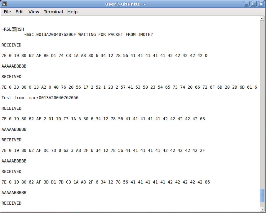
Figure 5.
The first packet comes from the iMote2. The length is 0x19 (25
décimal) including the 0x80 command code and excluding the
last byte which is the checksum. The 14th byte is the option byte
(see the XBee RX API structure). Here its value is 0x6 so it is both
a broadcast address and a broadcast PAN because it is the way we
sent it in the C# code. Then, you can recognize in the next 4 bytes
the PAN ID 0x1234 and the 16-bit address 0x5678 on the sending
iMote2. Then it is easy to identify the real payload, i.e.
'AAAAABBBBB' which is 41414141414242424242 in hex format.
The second packet comes from WB that is using the Libelium API to
send the packet. The 14th byte is again the option byte that
indicates an address broadcast mode because we used the broadcast
64-bit address "000000000000FFFF" in the
xbee802.setDestinationParams
call. Then we can recognize the application ID
0x52, the fragment number 0x01, the first fragment indicator '#' and
source type 0x02 (because we use NI_TYPE) and then the source ID
"WASP" (0x57 0x41 0x53 0x50). Then we have a '#' delimiter that is
not documented but it is inserted by the Libelium API and we have to
take it into account before we find the real data "Test from
-mac:0013A20040762056". The application header is from the Libelium
802.15.4 programming guide.
Figure 6.
Therefore the procedure for receiving a packet is quite simple.
Suppose that we have in memory buffer all the raw data, the
code in WA (getRawData()) is then:
//
set the myRawData pointer, one could extract additional
information from the XBee header if required
myRawData=memory;
myRawData_len=i;
int dataStart;
// test whether the packet commes from a WaspMote with the
Libelium API
if (memory[14]==0x52 && memory[18]=='W' &&
memory[19]=='A' && memory[20]=='S' &&
memory[21]=='P') {
dataStart=23;
}
else {
dataStart=18;
}
// set the length of the real data
myData_len=i-1-dataStart;
// allocate a new buffer to copy the real data, plus one char
for the null-terminated character
myData = (uint8_t*) calloc(myData_len+1,sizeof(uint8_t));
for (int j=0; j<myData_len; j++)
myData[j]=memory[dataStart+j];
// set the null-terminated chaacter so one could diectly pint
the real data if it is a string
myData[i-1]='\0';
We provide 2 pointers: myRawData will point to the
beginning of the raw data, i.e. the frame delimiter 0x7E and myData
will point to the real data, which position depends on whether it is
a packet from an iMote or another Waspmote with the Libelium API. We
simple have to test for the application ID 0x52 and the source ID
string "WASP" in order to point to the correct position. The
reception of packets in WA is then performed as follows:
if
(XBee.available()) {
XBee.println("RECEIVED");
getRawData();
XBee.println((char*)myData);
//
free myRawData
free(myRawData);
myRawData=NULL;
//
myData, note that both memory buffers are independent
free(myData);
myData=NULL;
}
Don't forget to free both myRawData and myData
when you don't need then anymore. We also replace the checksum by a
'\0' character so that you could print the real data in ASCII form
if required. If you are using non ASCII data, then you have to cast
appropriately myData into whatever data structure
you used at the sending side. Beware of different size type and
little or big endian mode! Now, you can have a look at the whole
reception code in WA.
Note that there is a light version of the Libelium API that simply
send the payload without any additional information. In this case,
you have a pure 802.15.4 frame so if you receive it on an other
XBee, data should start at byte 14 if 64-bit address is used and you
normally do not have anything to do to get the payload.
iMote2 under .NET using the TinyOS format
The .NET framework for the iMote2 has some (limited) form of TinyOS
compatibility: the radio could be a TOSRadio in order to be
compatible with Mica2, MicaZ or TelosB platforms that mainly run
under TinyOS system. In the previous C# code for the iMote2, just
change the following lines:
Radio
radio
= new Radio(_rfChannel, _rfPower, 0x1234, 0x5678);
in
TOSRadio
radio
= new TOSRadio(_rfChannel, _rfPower, 0x1234, 0x5678);
and adds the following line before the radio.Send call:
radio.amType
=
50;
The value is not important, you just have to pick a value to specify
the Active Message (AM) type of TinyOS. This value will help us
identify where the real data starts in the received frame.
The same procedure than previously, connecting the XBee gateway to
get the raw data (after processing escaped characters however),
gives the following dump:
7e 00 17
80 62 af 00 d1 7d af 1a a8 2e 06 32 7d 41 41 41 41 41 42 42 42 42
42 29
which could be decoded as follows with the API frame structure used
by the XBee for XBee->Application communications.
7E: frame start delimiter
00: Length msb
17: Length lsb
80: RX packet (64bits)
Source address : 62 af 00 d1 7d af 1a a8
RSSI : 2e
Option : 06 Address broadcast PAN broadcast
Data : 32 7d 41 41 41 41 41 42 42 42 42 42
Checksum: 29
We can see that the payload part comes again with 2 additional bytes
(and not 4 without the TOSRadio). The first byte is the amType value
(0x32 is 50 in decimal) and the second byte is the default AM group
ID used by the .NET framework (0x7d is 125 in decimal).
It is quite possible to modify the Waspmote reception code to take
into account both iMote with and without TOS radio. One solution
could be to always use the default group ID of 0x7d and track this
value. If you avoid a PAN ID having 0x7d byte then a non-TOS radio
will not have 0x7d at byte 15. If you have 0x7d at byte 15, then you
can say that it is from an iMote2 with TOSRadio and then the data
start at position 16 and not position 18 when the non-TOS radio is
used. You can add more safety by also tracking the amType byte if
once again you use a predefined value (such as 0x32). This is a
bit tricky and not 100% reliable but it works as a workaround to
make iMote2 and Waspmote communicating altogether in the same
network.
It is possible to use a mote under TinyOS (I've tested with a TelosB
and MicaZ) using the alternative tkn154 IEEE 802.15.4 compliant protocol stack to
receive/sniff packets sent by an iMote2 because the default
ActiveMessage layer will probably not give the frame to the
application layer because of internal filtering mechanisms. To build
such a sniffer, just follow the instruction in TinyOS to build for a
TelosB the tinyos-2.x/apps/tests/tkn154/nonbeacon-enabled/TestPromiscuous
application. This will act as a sniffer. Be sure to be on the same
channel (change in TestPromiscuousC.nc
the RADIO_CHANNEL parameter). Output obtained with the Java
PrintfClient is
shown below:
> java
net.tinyos.tools.PrintfClient -comm serial@/dev/ttyUSB0:telosb
Frametype: Data
SrcAddrMode: 0
SrcAddr:
DstAddrMode: 2
DstAddr: 0xFFFF
DestPANId: 0x1234
DSN: 210
MHRLen: 7
MHR: 0x41 0x08 0xD2 0x34 0x12 0xFF 0xFF
PayloadLen: 12
Payload: 0x32 0x7D 0x41 0x41 0x41 0x41 0x41 0x42 0x42 0x42 0x42
0x42
MpduLinkQuality: 108
Timestamp: 1807868
As before, you can see in the payload the first byte which is the
amType value (0x32 is 50 in decimal) and the second byte is the
default AM group ID used by TinyOS (0x7d is 125 in decimal).
Note that you can use a TelosB mote under TinyOS with the tkn154
protocol stack to then communicate with WaspMote and Arduino boards
also. This is explained below.
Communication the other way: Waspmote to iMote2
Communications from a Waspmote to an iMote2 is also possible. We
will demonstrate this by using the same second Waspmote WB (the one
which sends "Test from -mac...") and a iMote2 connected to a Windows
PC. To dump the serial port on the PC, we use the SerialDump
program provided by Crossbow in their iMote2 .NET bundle. The iMote
runs a modified version of the XSniffer program (XSniffer is one of
the sample program of the Crossbow .NET bundle). This modified
version, we called myXSniffer, does not use TOS messages and adds 2
additional dumps of the serial port: an hex and an ASCII version (we
decided to use this solution in oder to not change the SerialDump
code). The C# code for myXSniffer can
be seen here. The following screenshot shows the reception by
the attached iMote2 of packets from the Waspmote WB. Click on the
image to get the full resolution image.
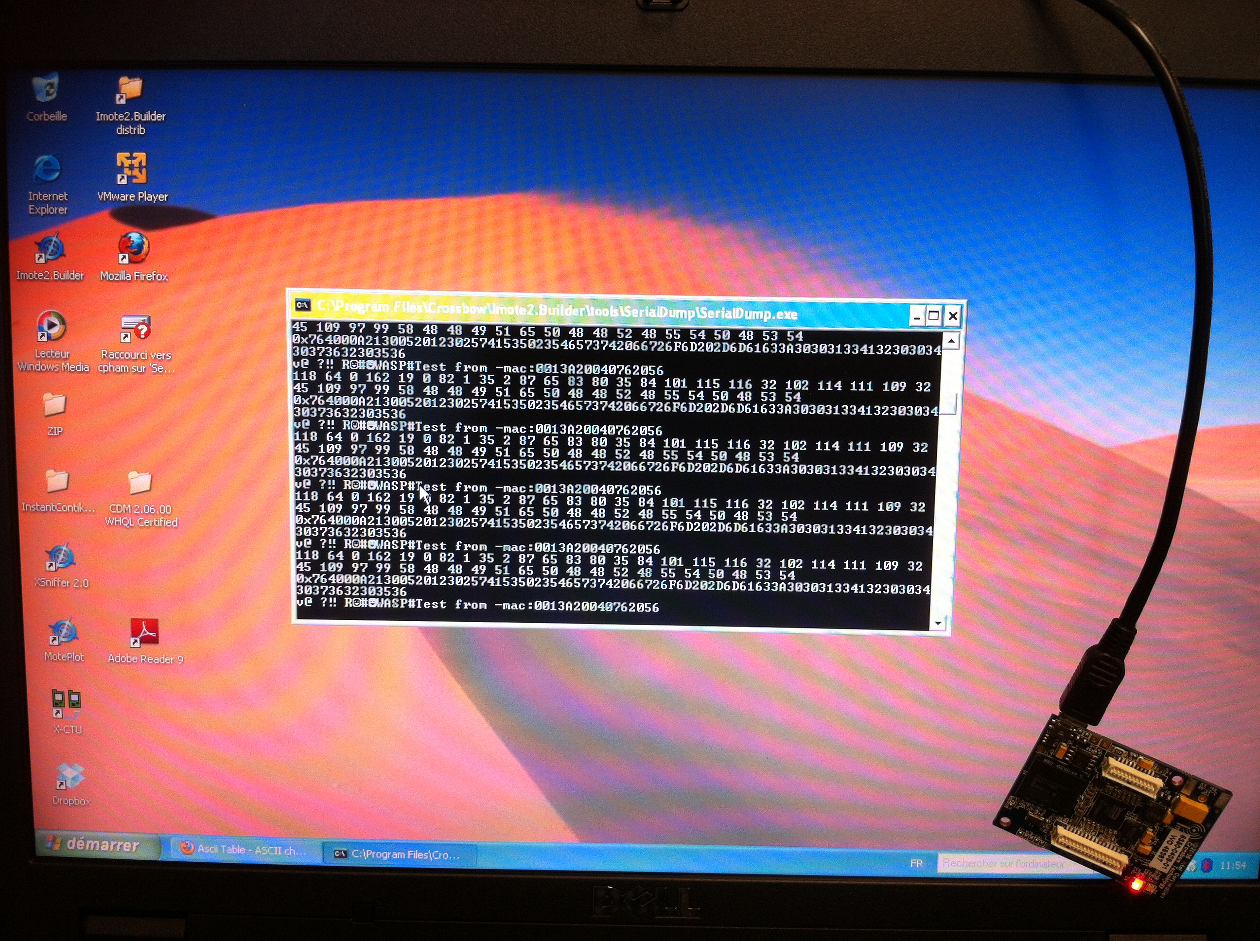
Figure 7.
You can see that the hex dump is :
76 40 00
A2 13 00 52 01 23 02 57 41 53 50 23 54 ...
The first 6 bytes is part of the source MAC address: 00 13 A2 00 40
76. Don't know exactely why the last 2 bytes (20 56) cannot be
obtained. The next 9 bytes, is the Libelium application header: 52
01 23 02 57 41 53 50 23. Once again, we can recognize the
application ID 0x52, the fragment number 0x01, the first fragment
indicator '#' and source type 0x02 (because we use NI_TYPE) and then
the source ID "WASP" (0x57 0x41 0x53 0x50). Again, we have the
terminating '#' delimiter that is not documented but it is inserted
by the Libelium API. We have to take it into account before we find
the real data "Test from -mac:0013A20040762056". Therefore, it is
quite possible on the iMote2 to point to the real data by skipping
the first 15 bytes when receiving the data. Once again, if you are
using non ASCII data, then you have to cast appropriately the
received data into whatever data structure you used at the sending
side. Be sure to know how the data are coded: little endian or big
endian!
Communication with Arduino board: (1) Arduino to Waspmote
We also have the Mega 2560 board from Arduino to test with. This
board can have 802.15.4 connectivity by plugging an XBee shield
(seems that the shield is from Libelium) with a Digi Xbee module
(serie 1). Arduino also have the equivalent of the USB-serial
gateway that work just like the Libelium gateway, and is fully
compatible with Waspmote node.
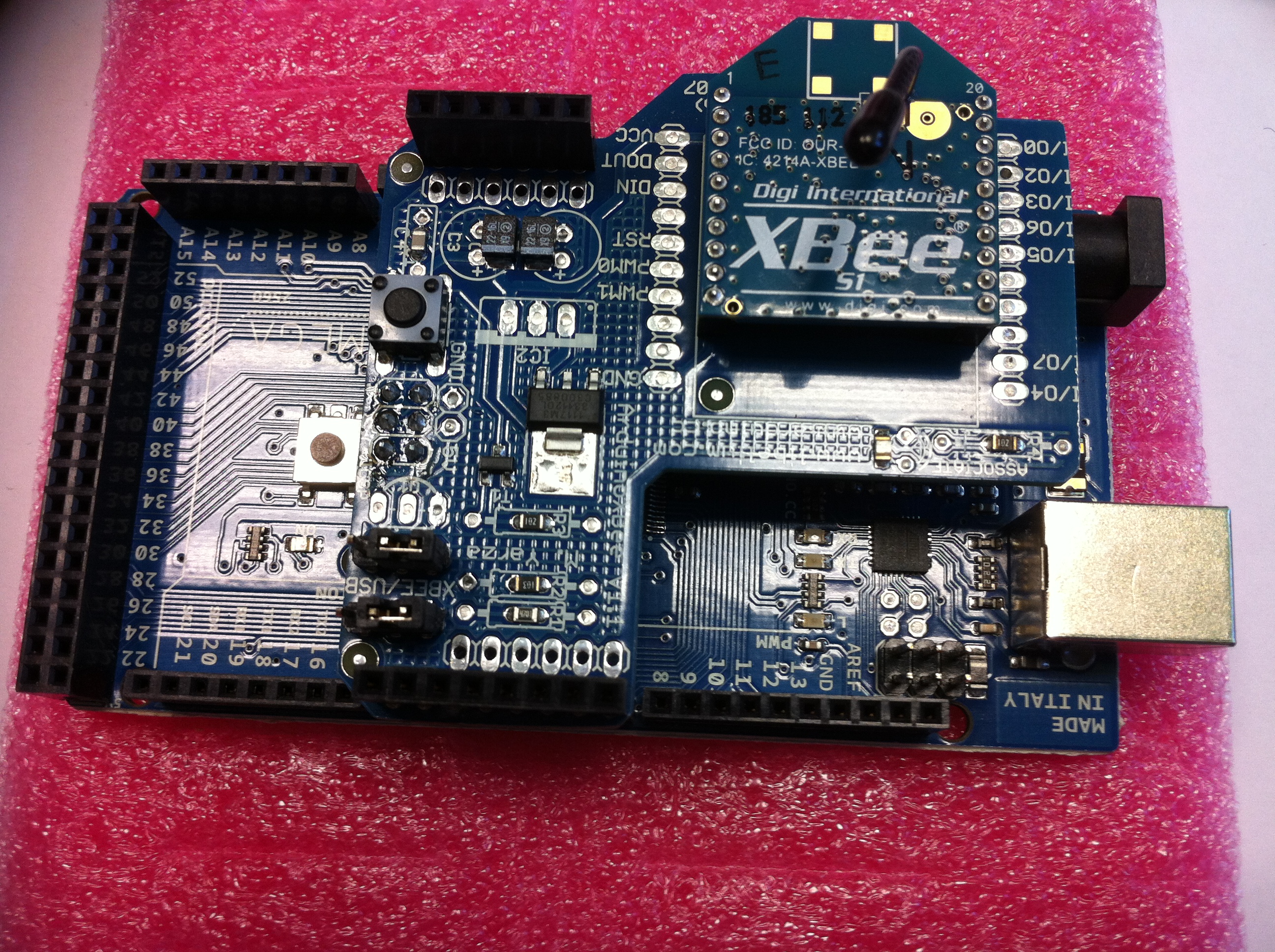
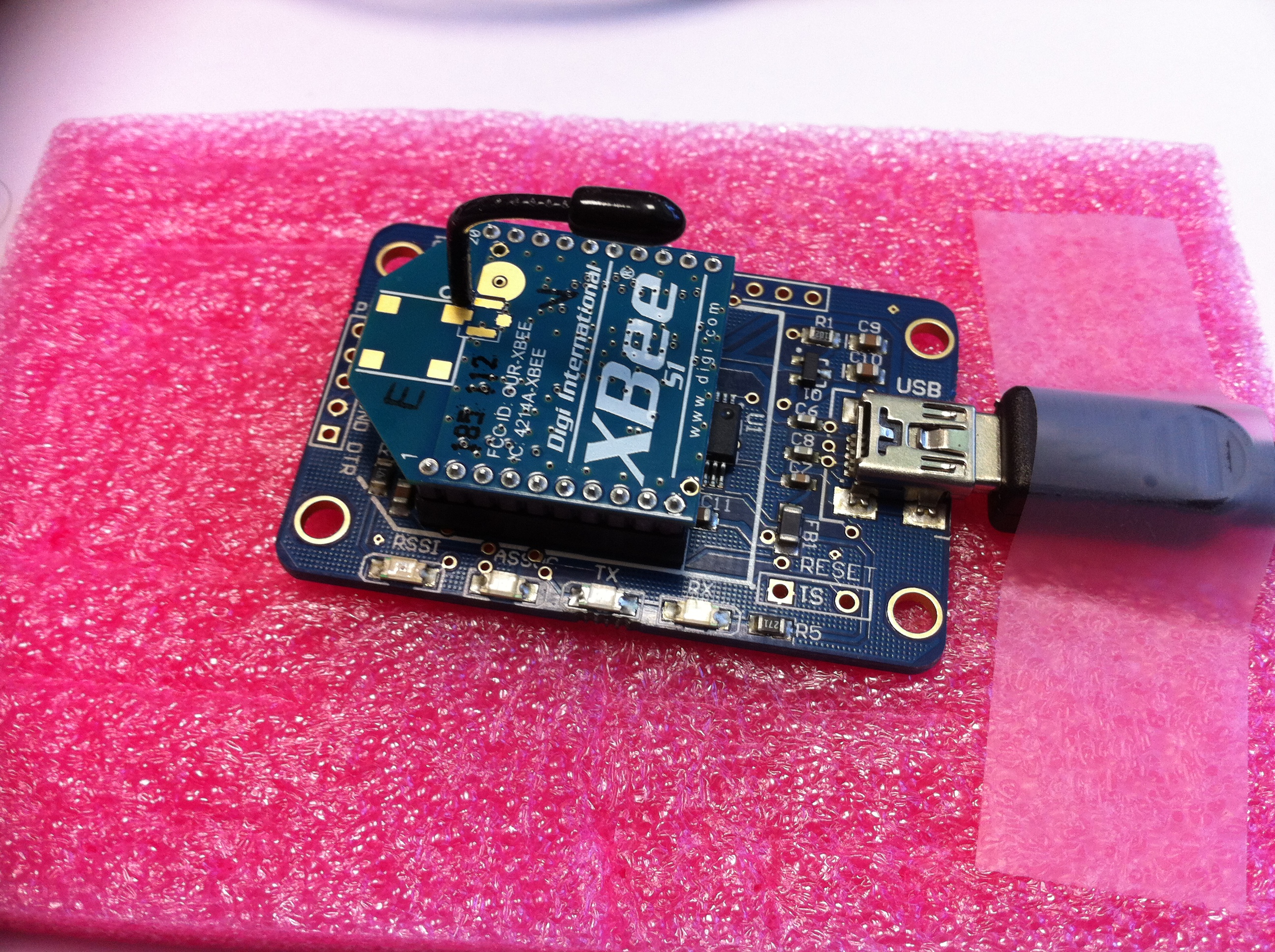
Figure 8.
Figure 9.
Like previously, make sure that the XBee module is set to the
correct configuration to allow physical connectivity:
atid1234
atchd
atmm2
atmyffff
atap2
atee0
atbd5
atwr
Note that once you issued the atbd5 command that put the XBee
module to work at 38400 bauds you may have to reconfigue your serial
tool (minicom for instance) to that baud rate.
We will use a library for using the XBee module with API mode which
is more convenient than the AT command mode that is used by the
original Arduino library. This XBee API library can be donwloaded
from http://code.google.com/p/xbee-arduino/.
Current version is 0.3. You can also check this
page to see how this library offers communication primitives
to Arduino board using the XBee module.
This XBee API library uses NewSoftSerial library from http://arduiniana.org/libraries/NewSoftSerial/
which is now included in the
Arduino IDE core library (as SoftwareSerial) if the version
is equal or higher than 1.0, which should be the case if you get the
latest Arduino IDE which is 1.0.1 released on May 21st, 2012.
Using this API, here is a simple code taken from
http://code.google.com/p/xbee-arduino/ to send a packet:
//
Create an XBee object at the top of your sketch
XBee
xbee = XBee();
// Tell
XBee to start Serial
xbee.begin(9600);
//
Create an array for holding the data you want to send.
uint8_t
payload[] = { 'H', 'i' };
//
Specify the address of the remote XBee (this is the SH + SL)
XBeeAddress64
addr64
= XBeeAddress64(0x0013a200, 0x403e0f30);
//
Create a TX Request
ZBTxRequest
zbTx
= ZBTxRequest(addr64, payload, sizeof(payload));
// Send
your request
xbee.send(zbTx);
We will then use this API to have a simple sending program which
does roughly the same thing than previously (i.e. sending "Test from
-mac:0013A20040762056"). For the moment, the MAC address is
statically fixed but it is probably possible to get it from the XBee
module using the XBee API to send the appropriate AT commands (atsh
and atsl to get respectively the msb and lsb of the 64-bit address).
The complete code for this test program to be compiled and uploaded
from the Arduino IDE is here.
Here is a .zip file
that you copy into your Aduino's IDE sketch folder and unzip it. As you can see in the source
code, we use AT command to
read the MAC address of the XBee module. This part is not important
for the communication issue that we are addressing here, but if you
are not familiar to AT command and want to know more on this, you
could read the following XBee page.
Important note, taken from
http://code.google.com/p/xbee-arduino/
The Arduino has only one serial
port which must be connected to USB (FTDI) for uploading sketches
and to the XBee for running sketches. The Arduino XBee Shield
provides a set of jumpers to direct Serial communication to either
the USB (Arduino IDE) or the XBee. When using the XBee Shield you
will need to place both the jumpers in the USB position prior to
uploading your sketch. Then after a successful upload, place the
jumpers in the "XBEE" position to run your sketch. Always remember
to power off the Arduino before moving the jumpers.
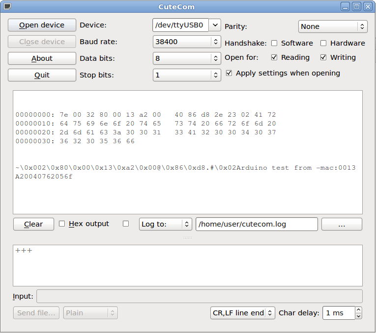
Figure 10.
Once again, we can use minicom (or alternatively cutecom, as shown
in figure 10, which can output the hex values) to see the raw data
received by an XBee gateway. Since there is no extra header
introduced by the Xbee API (nothing like the full Libelium API for
instance) the raw data strictly follows the structure of the Digi
XBee receive frame illustrated in figure 4. Note that a WaspMote
with the light Libelium API is fully compatible with an Arduino
since both use the XBee module without introducing any additional
overheads.
It is possible to modify the previously Waspmote reception code to
take into account also data sent from Arduino boards that strictly
follow the Digi XBee frame structure. In the following
version, we check whether byte 14th and byte 15th have
respectively the value of 0x34 and 0x12 (the PAN ID) in which case
it is most probably a packet from an iMote2 (without TOS header),
otherwise it is a packet from a pure XBee module such as the Arduino
XBee API without any additional header. In the figure below, we can
see that we can successfully receive simultaneously from an iMote2
(the 'AAAAABBBBB' payload), a Waspmote with Libelium API (the 'Test
from -mac:0013A20040762056' payload) and from a Mega 2560 Arduino
board (the 'Arduino test from -mac:0013A20040762056' payload).
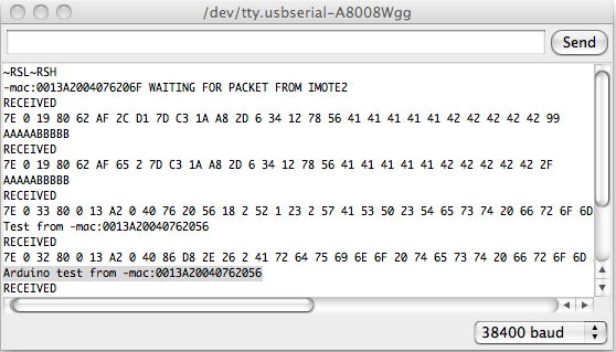
Figure 11.
Communication with Arduino board: (2) Waspmote and iMote2 to
Arduino
Normally, data from a Waspmote to an Arduino should carry the
application header of the Libelium API. So, if we use the same
convention then previously of using 'WASP' as the node identifier
for Waspmote node you could just skip the application header that
should look like:
... 52 01
23 02 57 41 53 50 23 ...
To verify this statement, we wrote a simple sniffer program for the
Arduino using the XBee API. The
simple
sniffer code can be find here. Once again, here is a .zip file that you can
copy into your Arduino's IDE sketch folder and unzip it. Compile and
upload the sniffer program, then open the serial monitor (or any
serial tools such as minicom) to get the following information:
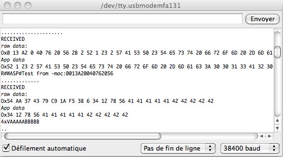
Figure 12.
The sniffer program prints 3 informations: (1) data (hex format) got
with getFramedata()
function, (2) data (hex format) got with getData() function and (3)
data (ASCII format) got with getData() function.
The first packet is received from our Waspmote WB. You can see that
the "raw data" section includes the source MAC address followed by
the RSSI and the option byte (that indicate an address boadcast here
0x2). Actually, this is the cmdData part of figure 4 from the
XBee module. Then you have the data from the application layer that
you can also see in the "App data" section. Before the real payload,
we can recognize the Libelium application header. So our
suggestion was true and you just have to skip this header to get the
real payload.
The packet is received from our iMote2 that again contineously sends
the 'AAAAABBBBB' payload. Very similarly to the iMote2->Waspmote
case (except that with the XBee API on the Arduino the raw data does
not include the frame start delimiter, the frame length and the XBee
API identifier) we can recognize in the first 6 bytes of the raw
data something similar to an 64-bit address field but it is varying
so this information seems not to be reliable. Then we can see that
the PAN ID 0x1234 and the 16-bit address of 0x5678 becomes part of
the payload so you just have to skip these bytes to get the real
payload.
As part of a master project, a group of students of University of
Pau (year 2012-2013) wrote this reception code
that allows an Arduino to receive the real payload from Libelium,
Imote and, of course, other Arduino.
Communication with Arduino board: (3) Arduino to iMote2
Communication from an Arduino to an iMote2 is very similar to the
Waspmote to iMote2 case. The only difference is that the application
header is not present therefore the real data starts right after the
first 6 bytes that, once again, represent part of the source MAC
address. Once again, I don't know exactely why the last 2 bytes
cannot be obtained. Therefore, for an Arduino board, you can just
skip the first 6 bytes. Remember that for an Waspmote, we found that
we have to skip 15 bytes. It is possible to distinguish between data
from an Arduino and data from a Waspmote if we use the same
convention then previously of using 'WASP' as the node identifier
for Waspmote node. In this case, 'WASP' should starts at byte 10,
otherwise it is most probably a packet from an Arduino.
CC2420 Motes (iMote2, TelosB, MicaZ,...) under TinyOS to XBee
(WapsMote or Arduino), see text in red for
the opposite way (XBee to TinyOS)
TinyOS with ActiveMessage
The default TinyOS configuration uses ActiveMessage to communicate
and the current version of TinyOS uses by default interoperable
frames (IFRAME) to be able to interoperate with non-TinyOS network.
By default, TinyOS proposes the TINYOS-6LOWPAN network identifier
which has value 0x3F (see TEP125
and TEP126,
as well as tinyos-2.x/tos/chips/cc2420/cc2420.h).
In order to communicate between motes, at the 802.15.4 level the
motes themselves must be in the same PANID. The fact is that under
the ActiveMessage stack, the correspondance between the
ActiveMessage various addresses and the 802.15.4 addresses is a bit
tricky. After several tests with a promiscuous sniffer (the one
described previously with the tkn154 stack) here are our
conclusions:
- the DEFAULT_LOCAL_GROUP variable will define both the source
and destination PANID, because it seems that TinyOS only support
intra-PAN communication to the best of our knowledge, but it has
to be defined at the highest level
- the TinyOS node id will be mapped to the 16-bit 802.15.4
source address
So if you want your mote to be on PANID 0x3332 and having a 16-bit
address of 0x6287 then you have to issue the following command for
compiling and installing the program on the motes, here a TelosB
mote:
>
DEFAULT_LOCAL_GROUP=0x3332 make telosb
> make telosb reinstall.0x6287 bsl,/dev/ttyUSB0
Unfortunately, our first tests shown that the 16-bit PANID address
is not correctly interpreted by TinyOS and it appeared that only the
lower part of the 16-bit address is taken into account by TinyOS.
This has been verified with the sniffer that showed that the source
PANID is set to 0x32 and not 0x3332. After verification, this is
confirmed in tinyos-2.x/tos/types/AM.h
where nx_am_group_t and
am_group_t are
defined as nx_uint8_t
and uint8_t respectively.
So in order to take into account the 16-bit PANID, our first
solution was to change these types to nx_uint16_t and uint16_t respectively. After
these changes and recompilation, the upload of the program on the
mote will assign to the CC2420 module the requested 16-bit PANID.
Now, if we look at what is captured by the sniffer, we have
something like:
Frametype: Data
SrcAddrMode: 2
SrcAddr: 0x6287
SrcPANId: 0x3332
DstAddrMode: 2
DstAddr: 0xFFFF
DestPANId: 0x3332
DSN: 170
MHRLen: 9
MHR: 0x41 0x88 0xAA 0x32 0x33 0xFF 0xFF 0x87 0x62
PayloadLen: 12
Payload: 0x3F 0x02 0x41 0x41 0x41
0x41 0x41 0x42 0x42 0x42 0x42 0x42
MpduLinkQuality: 108
Timestamp: 58237590
In the payload we can see that there are 2 extra bytes compared to a
pure 802.15.4 payload. The first byte 0x3F is the TINYOS-6LOWPAN
network id as explained above. The second byte 0x02 is the AM_ID
that you give to your application when writing new AMSendC(MY_AM_ID) to define
the ActiveMessage sender component. In summary, if you wants to
correctly interpret a frame sent by a mote under TinyOS
ActiveMessage, you could track the TINYOS-6LOWPAN network id and
check whether the AM_ID is one value that you have defined for your
application.
Unfortunately, changing the width of nx_am_group_t and am_group_t introduces some
incompatibility issues with tools such as PrintfClient. So if you just want to
stick with the default TinyOS distribution, you can just use only
8-bit PANID for your XBee modules. In this way, the PANID value for
TinyOS will be the same than the one of your XBee. If you still want
to have 16-bit PANID, which is the standard in 802.15.4 networks,
here is our final solution that avoids changing the width of nx_am_group_t and am_group_t therefore
preserving the compatibility with the other TinyOS tools. Our
solution consists in changing in the tinyos-2.x/tos/chips/cc2420/control/CC2420ControlP.nc
file the following statement in the Init.init() function:
m_pan = call
ActiveMessageAddress.amGroup();
into
#ifdef
DEFAULT_LOCAL_GROUP
m_pan = DEFAULT_LOCAL_GROUP;
#else
m_pan = call ActiveMessageAddress.amGroup();
#endif
Then in the Makefile
you can add the compilation flag in the usual manner:
CFLAGS +=
-DDEFAULT_LOCAL_GROUP=0x3332
It has been tested on both TelosB and MicaZ platforms.
Actually, it is also possible to communicate
from a WaspMote or Arduino to a mote under TinyOS ActiveMessaging
system. To do so, just insert 0x3F and an 8-bit value for an
ActiveMessage identifier before your payload to make the TinyOS
mote with ActiveMessage being able to retrieve the packet. For
instance, if you want to send "hello" then build the following
payload: 0x3F 0x02 'h' 'e' 'l' 'l' 'o'. On the XBee module you
MUST be in Mac Mode 2 (AT MM2) and MUST have a 16-bit network
address (AT MY) that is different from 0xFFFF because otherwise
TinyOS with the CC2420 (MicaZ, TelosB, iMote2,...) will
incorrectly understand the packet. In my case, I'm using the last
4 digit of the 64-bit address of the XBee module to define the
16-bit address. If you do so, you will be able to correctly
receive the payload on the TinyOS mote which is "hello", here is a
portion of the slightly modified TinyOS BaseStationP.nc:
event message_t
*RadioReceive.receive[am_id_t id](message_t *msg,
void *payload,
uint8_t len) {
id = call RadioAMPacket.type(msg);
if (id==0x02) {
uint8_t k;
printf("Got: ");
for (k=0; k<len; k++)
printf("0x%02X ", *(uint8_t*)(payload+k));
printf("\n");
}
else
printf("Rcv(AMID %u) not
from expected AMID 0x02\n", id);
printfflush();
return msg;
}
So if you forge a packet 0x3F 0x02
'h' 'e' 'l' 'l' 'o' you will see:
Got: 0x68
0x65 0x6C 0x6C 0x6F
and if you send 0x3F 0x05 'h' 'e'
'l' 'l' 'o' you will get:
Rcv(AMID
5) not from expected AMID 0x02
We can sniff what is
actually sent on the air (when the AM ID is 0x02) with the
promiscuous sniffer where the 16-bit address of my XBee module is
set to 0x205B and I'm sending to network address 0x0001:
Frametype: Data
SrcAddrMode: 2
SrcAddr: 0x205B
SrcPANId: 0x3332
DstAddrMode: 2
DstAddr: 0x01
DestPANId: 0x3332
DSN: 131
MHRLen: 9
MHR: 0x61 0x88 0x83 0x32 0x33 0x01 0x00 0x5B 0x20
PayloadLen: 7
Payload: 0x3F 0x02 0x68 0x65 0x6C 0x6C 0x6F
MpduLinkQuality: 107
Timestamp: 72145824
TinyOS with 802.15.4 stack
Now, it is also possible to have a pure 802.15.4 behavior with
TinyOS without the extra 2 bytes. As said previously, TinyOS can
have 802.15.4 MAC behavior if the tkn154 protocol stack is used. Here we are going
to flash one TelosB (noted telos1) mote with the previously tinyos-2.x/apps/tests/tkn154/nonbeacon-enabled/TestPromiscuous
application. An other TelosB mote (noted telos2) will be flashed
with the tinyos-2.x/apps/tests/tkn154/nonbeacon-enabled/TestIndirectData/Coordinator
application. Normally this application use indirect transmission but
in our case we will use direct tranmission by removing the TX_OPTIONS_INDIRECT
flag in the SendIndirectData()
function of TestIndirectDataCoordC.nc.
In app_profile.h,
we use RADIO_CHANNEL= 0x0C and PAN_ID=0x3332. We set DEVICE_ADDRES
to 0xFFFF for broadcast and left the COORDINATOR_ADDRESS unchanged.
It is possible to indicate a 16-bit destination short address here
and you will have to configure the receiving XBee module accordingly
(ATMY6288 for instance).
To built the executable, just type in tinyos-2.x/apps/tests/tkn154/nonbeacon-enabled/TestIndirectData/Coordinator:
> make telosb
> make telosb reinstall.0x0001 bsl,/dev/ttyUSB0
Note that it has also been tested with a MicaZ sender. Now, assuming
that telos1, the sniffer, is now connected on /dev/ttyUSB0, run:
> java
net.tinyos.tools.PrintfClient -comm serial@/dev/ttyUSB0:telosb
to have the sniffer running. At the same time, use a WaspMote with
the sniffer program with an XBee configured on radio channel 0x0C
and PANID 0x3332 to get the frames sent by telos2. Figure below
shows a screenshoot of a serial tool (Serial Tools on MACOSX)
connected to the WaspMote to get the output of the sniffer WaspMote.
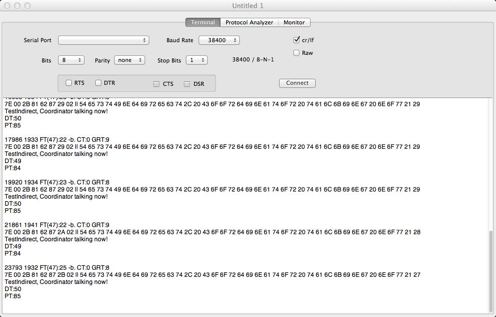
If we look at the last line for instance, the XBee raw data is:
7E 00 2B 81 62 87 2B 02
54 65 73 ...
This is interpreted as:
7E: frame start delimiter
00: Length msb
2B: Length lsb
81: RX packet (16bits)
Source address : 62 87
RSSI : 2B
Option : 02 Address broadcast
Data : 54 65 73 ...
Checksum: 27
The payload is captured correctly by the WaspMote as it is a pure
802.15.4 payload. If we look at what is captured by telos1 (the
promiscuous sniffer), we can see the following information:
Frametype: Data
SrcAddrMode: 2
SrcAddr: 0x6287
SrcPANId: 0x3332
DstAddrMode: 2
DstAddr: 0xFFFF
DestPANId: 0x3332
DSN: 170
MHRLen: 9
MHR: 0x61 0x88 0xAA 0x32 0x33 0xFF 0xFF 0x87 0x62
PayloadLen: 38
Payload: 0x54 0x65 0x73 0x74 0x49 0x6E 0x64 0x69 0x72 0x65 0x63
0x74 0x2C 0x20 0x43 0x6F 0x6F 0x72 0x64 0x69 0x6E 0x61 0x74 0x6F
0x72 0x20 0x74 0x61 0x6C 0x6B 0x69 0x6E 0x67 0x20 0x6E 0x6F 0x77
0x21
MpduLinkQuality: 108
Timestamp: 58237590
Frametype: Acknowledgement
SrcAddrMode: 0
SrcAddr:
DstAddrMode: 0
DstAddr:
DSN: 170
MHRLen: 3
MHR: 0x02 0x00 0xAA
PayloadLen: 0
Payload:
MpduLinkQuality: 107
Timestamp: 58237720
It is quite interesting to see that the CC2420 of the TelosB in
promiscuous mode can be used as a radio sniffer since we also
captured the ACK sent back by the XBee module. This is not
possible with an XBee because the XBee firmware does not give
access to these ACK frames.
When using the TKN154 stack, communicating
from a WaspMote or Arduino to a mote under TinyOS becomes
straightforward. You can either use 16-bit or 64-bit source
address (by setting MY to 0xFFFF) and use either 16-bit or
64-bit destination address. Once again, in any case, you need to
set your XBee module in Mac Mode 2 which is the pure 802.15.4
mode (no Digi header).
Summary
In summary, we have been able to communicate between various sensor
motes: .NET iMote2, TinyOS TelosB & MicaZ, Waspmote and Arduino.
It is a bit tricky to make all of them communicating simultaneously
but it is possible if some conventions are used to identify the
provenance of data packets. With TinyOS, the usage of the tkn154 protocol
stack will allow easy bi-directional commnication, i.e.
TinyOS<->XBee, otherwise, if ActiveMessage is used, you need
to take into account the 2 additional bytes used by the
ActiveMessaging system to generate then for XBee->TinyOS and to
remove them for TinyOS->XBee.
Miscelleneous
Here is a nice
tutorial on how to install the latest Arduino IDE on Ubuntu
Linux.
Perspectives
It may be possible to use the Libelium XBee library with Arduino
boards by importing (and probably modifying some lines) the
appropriate code into the Arduino IDE.
Hope this helps. Enjoy!
C. Pham.