last update: March 24th, 2015.
This document provides information on our research on wireless
sensor networks and multimedia surveillance application with image
and audio sensing. It will show examples of demo and describe our
test-bed. You are encouraged to look at the following resources to
get more familiar with our research.
Selected recent publications (see full
list):
Selected recent presentations/talks/tutorials (see full
list):
Our research uses various sensor boards and radio modules:
Libelium WaspMote, Arduino MEGA, XBee module, Crossbow
MicaZ/iMote2, AdvanticSys TelosB. You are also encouraged to look
at the following resources:
NEW: see our
image sensor board built around an Arduino Due and an
uCamII (from 4D system)!!
We started our research on image transmission with iMote2 mote
with IMB400 multimedia board but quickly moved to a more flexible
and generic solution as we are mainly interested in networking
issues related to data-intensive applications. Therefore we
adopted the following architecture:
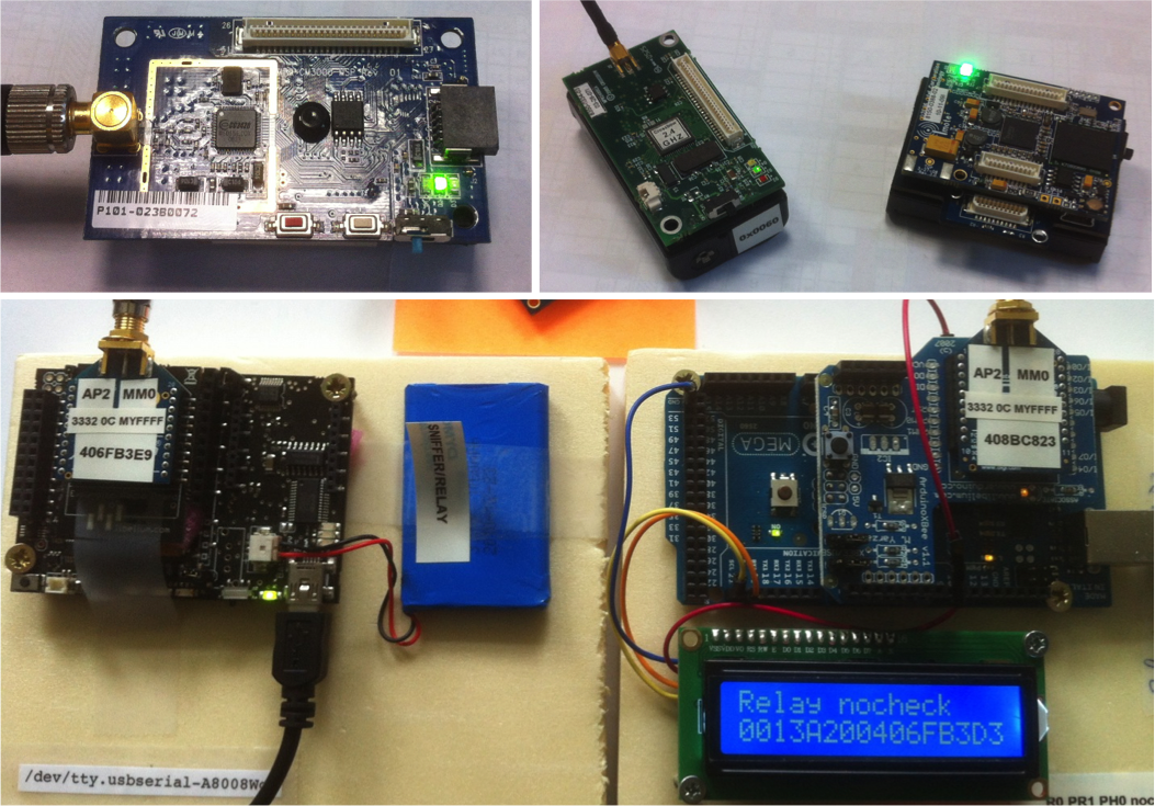
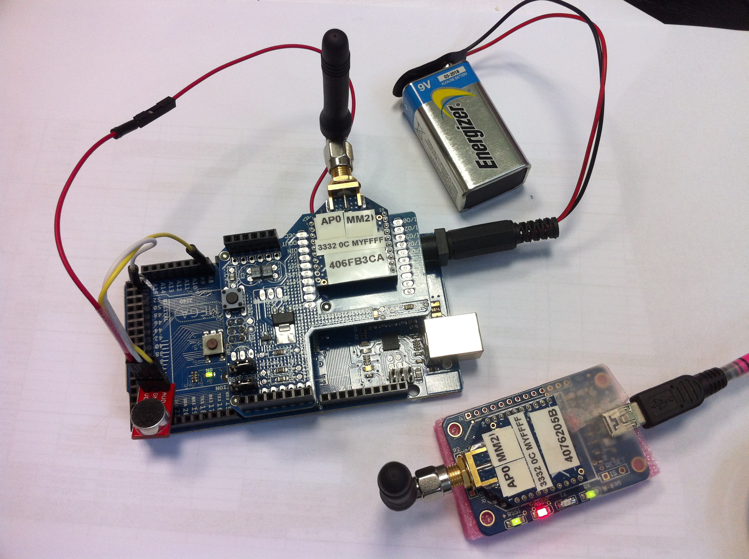
Figure below shows from left to right (source, relay, sink) the 3
main components of our test-bed
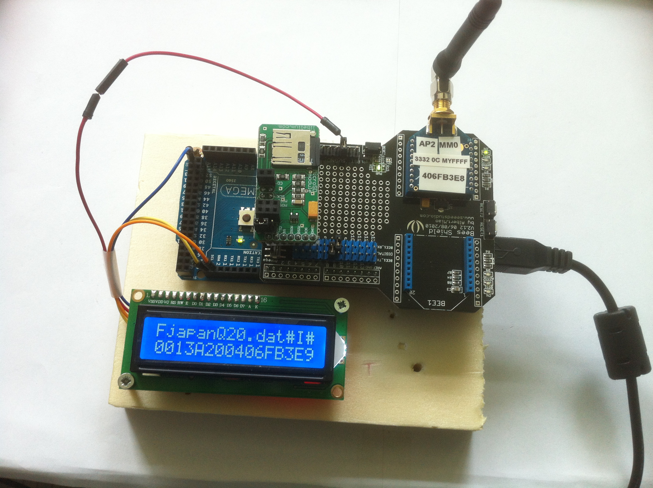
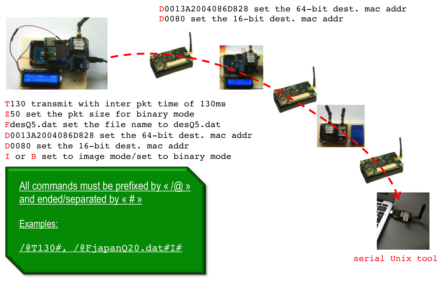
The source node accepts a number of command (ASCII form) to configure the node prior to transmission. All commands must start with '/@' and end with '#'. You have to define the name of the file that the source will send (command /@F#. If the file is an image, you have to use image mode (command /@I#). More information on the specific image format we use can be found below. Note that all other type of binary file (jpg, bmp, wav, spx, ...) must be treated in binary mode (command /@B#). Once the destination node is set with command /@D# (either 64-bit or 16-bit destination address can be specified) then you can trigger the file transmission with command /@T# that accepts an inter-packet time expressed in ms: /@T130# will wait 130ms between each packet. You can specify the maximum application payload with command /@Z#.
Note A: the default behavior of the source node is to add 5
framing bytes. The first 2 bytes are 0xFF 0x55->0x59 for
binary packets and 0xFF 0x50->0x54 for image packets. Then
comes a sequence number, the quality factor and then the packet
size
Note B: the source node, when operating in binary mode,
in addition to the 5 framing bytes, uses a 4 bytes
header in each packet to store the file size (2 bytes) and the
offset in the file (2 bytes).
We recently add the support of flow id in order to make multi-source scenario possible in a very simple way: you can specify a flow id number that will be use to create specific framing bytes. Use command /@L0-4# to specify a flow id (sort of a label) between 0 and 4. For instance, if the flow id is 2 and the mote runs in image mode, then the framing bytes will be 0xFF 0x50+2, i.e. 0xFF0x52. If the mote runs in binary mode, then the framing bytes will be 0xFF 0x55+2. This feature is useful when used in conjuntion with the relay node's feature to also forward incoming packets based on the flow id. See this page to have more information all relay nodes.
The relay node could be any type of sensor node with an 802.15.4
compatible radio without any application or protocol header (raw
mode). We do have relay node source code for Crossbow MicaZ and
iMote2 as well as for AdvanticSys TelosB mote. Check this page to have more information and all
the source code.
Each relay node accepts 2 main commands: /@R# and /@D#. /@R# is used to dynamically toggle the MAC layer ack mechanism or not: /@R0# disables MAC layer ack and /@R1# enable MAC layer ack. The /@D# is similar to the previous /@D# command for the source node: either 64-bit or 16-bit destination address can be specified.
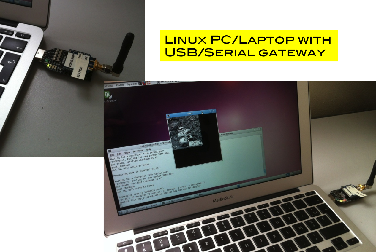
The sink node is a Linux-based machine with either an XBee
gateway or a TelosB BaseStation. A python script will read from
the serial port the incoming data and will write then on standard
output. display_image
will then be used to read from standard input to receive and
display images in the specific encoding scheme. For binary audio XBeeReceive will
be used. The available options will be described later on for each
case: image or audio file.
We use an XBee radio connected to a Linux-based machine to send
the various ASCII form commands. This tools allows various option
as explained below:
USAGE: ./XBeeSendCmd -baud baudrate -p dev [-L][-DM][-at] -tinyos -tinyos_amid id_hex -mac|-net|-addr|-b -size s -n n -t t
USAGE: -baud, set baud rate, default is 38400
USAGE: -p /dev/ttyUSB1, set setial port, default is /dev/ttyUSB0
USAGE: -L, insert Libelium API header for WaspMote under full Libelium API
USAGE: -DM, specify DigiMesh firmware
USAGE: -at, send remote AT command: -at -mac 0013a2004069165d ATMM
USAGE: -tinyos to forge a TinyOS ActiveMessage compatible packet (0x3F0x05 are inserted)
USAGE: -tinyos_amid 6F, to set the ActiveMessage identifier to 0x6F (0x05 is the default
USAGE: -flowid 1 to set flow id to 1 (0xFF0x51 are inserted)
USAGE: -mac 0013a2004069165d, set 64-bit dest. MAC address
USAGE: -net 5678, set 16-bit dest. address
USAGE: -addr 64_or_16_bit_addr, set either 64-bit or 16-bit dest. address
USAGE: -b, use broadcast
USAGE: -size 50, set packet size to 50 bytes
USAGE: -n 10, send 10 packets
USAGE: -t 500, set 500ms between each packet
For the moment, the simplest usage to send a command is:
> XBeeSendCmd –addr 0013A2004086D835 /@T130#
You can send an ASCII string for test purpose:
> XBeeSendCmd –addr 0013A2004086D835 "hello world"
or a packet of size 50 filled with '*' characters:
> XBeeSendCmd –addr 0013A2004086D835 -size 50
You can use XBeeSendCmd to
also issue packet with framing bytes in order to test the
various possibilities associated to flow id (multi-source and
multi-path scenario for instance). Suppose you want to send a
packet with "hello" content but prefixed with framing bytes,
0xFF0x52, indicating a flow id number 2 of an image source for
example:
> XBeeSendCmd –addr 0013A2004086D835 -flowid 2 "hello"
If you want to
indicate flow id number 2 of a binary source (flow id from 0x55
to 0x59 in our convention), then issue the following command to
have framing bytes of 0xFF0x57:
> XBeeSendCmd –addr 0013A2004086D835 -flowid 7 "hello"
Fast zonal DCT for energy conservation in
wireless image sensor networks
Lecuire V., Makkaoui L., Moureaux J.-M.
Electronics Letters 48, 2 (2012), pp125-127
Here are the steps for using this program:
> g++ -o JPEGencoding JPEGencoding.c
> ./JPEGencoding original_image_file.bmp
The image must have the same horizontal and vertical
dimension!
Here is a typical output for the following example:
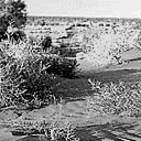
> ./JPEGencoding desert-320x320-gray.bmp
Compression rate : 1.30 bpp
Packets : 302, Packets: 012E
Q : 50, Q: 0032
H : 320, H: 0140, V : 320, V: 0140
Real encoded image file size : 16595
Packets indicates in decimal and hexadecimal the number of packets
that have been generated. The other parameters are Q, the quality
factor, and H and V that are respectively the horizontal and
vertical size of the image. The real encoded image file size (in
bytes) is also indicated. This is the real total amount of bytes
that will be placed in the payload of the packets. You can
optionally mention the maximum payload size per packet (64 by
default) and the quality factor (by default 50, should be between
1 and 100). For instance:
> ./JPEGencoding -MSS 90 -Q 40 original_image_file.bmp
The first example above used the default value so was MSS=64 and
was Q=50. The program produce a .dat file which name is composed
of the MSS, the quality factor, the number packets and the real
size in bytes. With the previous example, the produced file name
would be: desert-320x320-gray.bmp.M90-Q40-P177-S14523
The structure of the trace file generated by the program is as
follows:
XXXX: number of packets
XXXX: horizontal image size
XXXX: vertical image size
XXXX: quality factor
then XXXX XX XX .. .. XXXX XX XX ...
where the XXXX (4 hex digit string)
indicates the number of samples XX (2 hex digit string) that
represent the first packet. The size of the first packet is then XXXX. This pattern is repeated until the
end of the file. The program produce a .dat file which name is
composed of the MSS, the quality factor, the number packets and
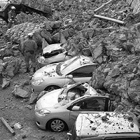
the real size in bytes. Here are the various images that we are
using in our tests:
For example, here is the content of the 128x128 image encoded
with Q=5 and MSS=90. There are 12 packets in total and the first
packet is of size 0x0059=89 bytes, then the next packet is of size
0x0056=86 bytes, ...
000C 0080 0080 0005 0059 00 00
CD E5 43 C2 3A C8 1B D0 A0 E7 2A C7 D1 6C EE 60 FD 5A A8 AB 53
87 C0 29 D4 85 01 43 B0 95 C5 93 7C A8 65 9C 1C 13 F4 16 CA 02
27 08 EB 4A 38 AB 06 06 22 8E 74 61 EA 18 4A BD EB 77 0D 46 D9
8F 8B 05 92 E1 EE D9 9A 98 D4 A3 3F 83 16 E0 D0 6B 87 14 48 58
4E 13 7F 0056 00 20 D5 BE 0B 70 DF 3C 0F 1B 48 13 93 9E 73
45 03 94 1E 9B A5 0B BB CF 52 04 4D 3E 88 36 B6 02 77 CE 9F F8
32 42 18 A8 F8 AA 79 9E 35 20 A0 A5 98 FE 32 16 1E 97 90 47 87
EC 69 61 60 7D AB 96 B9 AC CD B4 B8 5D B9 88 23 60 20 32 44 30
8A DA 5B A4 00 46 36 15 0057
00 32 E8 24 33 13 48 69 28 66 73 BD 03 3E 2F 37 CC CF E4 9E A9
1E CD EB 45 36 B6 12 18 FA 6A BA A9 94 1A 95 EB 49 50 CD A1 77
C2 8E 73 21 CB DC 5D 06 E4 29 A3 B6 70 C5 E0 F9 C4 62 16 9F 94
98 CD 1C AE 0D AF 7E DE 24 44 33 FB 54 6A 08 A8 1A 70 9E A2 DA
50 AC 27 0056 00 45 E8 45
44 23 09 42 33 69 5E 96 2E 7E 7F EB 8D 59 88 9F 23 9E 4F B2 77
62 30 8B BA AC 73 89 2F 3D 18 91 73 FC CF BF 36 DC B1 86 22 98
02 93 C7 86 01 06 36 85 89 BE 2F 01 6E 57 B0 51 82 AE 87 7B 43
80 42 5B E9 4B 78 58 CF 59 F8 56 29 C6 A8 1C 0C 72 09 97 0058 00 5B D9 2E 88 09 71 6D 35
C4 7A EA 22 DA DE 38 EF 8D 9C B2 A8 B4 F0 9C CA 1A 0E F5 A7 E6
2B 39 20 E6 07 67 34 CB 1F B1 BA C4 28 F0 69 EC 45 37 AF AF DE
E0 04 9A A8 CE 95 73 9A 75 B5 8E A1 F0 1C 2E DF 16 23 38 A1 2E
DA C6 72 3D 56 CF 7E D2 99 5E AE 12 DB 20 E2 C7 0058 00 6E E8 50 B3 86 C5 77 B9
97 57 8C AC CE 52 E1 D7 CD 4A 0D A2 B3 9B D2 DC 91 EA 63 9A 03
D5 2B 23 15 5C 1B 26 0E 0F 3C 82 4E 61 41 3E 9E 84 ED 54 4A ED
62 CC 8D 6D 71 66 60 46 F5 16 22 5D ED 7D 79 E8 46 FE 3C 6F 8C
71 88 EC EA 01 1C 73 E0 4A 3D 94 BE FC 14 C6 3F 0056 00 84 D3 27 D6 C1 A4 52 F8
F2 4C 83 6F 05 6E F7 91 32 F2 3F D7 9B 09 3E D6 F6 72 AA 63 0C
C1 DC 48 E2 8F DD 55 53 80 F0 94 C3 D4 5D 8D 27 F2 EE C2 80 F3
3F 55 8A 7F 47 BA 67 FA CB 17 16 EE 24 A2 72 FA E0 BA CA C7 0F
C6 07 0F 11 36 69 FA 7A FC 82 66 33 49 43 0058
00 A2 D5 CC 94 AA 76 33 99 15 B9 B9 8A B4 A3 58 D0 EA 64 4B 7F
2F F2 D6 B6 3F F0 D5 8A 09 EF 91 63 5B 32 3B 6A 75 16 48 E2 0C
A9 D1 8C D6 CA C3 27 3B B0 18 23 CA 76 9C BE F3 95 FF 4C 83 30
6D 56 D5 1D D6 3E C2 86 53 AB D7 40 82 27 56 62 9B B0 D2 CE 02
CB EA 3F BF 0059 00 B3 F0
6E F9 54 05 8B 78 89 78 5B D7 DC B6 FB 01 76 E8 96 A6 0B A4 C2
E0 CD B9 4D C5 43 35 C3 C1 83 D0 7A 92 4E 76 B0 16 60 C2 44 78
60 9C 0D 17 AA 1C EC 0E B5 83 01 CE 5A DA 13 F4 4F C0 EB 3F 00
84 D3 18 6B 08 6F 66 CB 76 A0 A5 8E 1F 37 75 88 BC 14 16 C6 DC
19 13 0058 00 C4 DE 9F C4
66 B8 0E 86 AA 0F FE 7F 3E FA 8B 54 26 AC DB 18 24 EC 47 A5 2C
B6 AE 02 14 1C AB 56 CF 87 51 BB 2D 2F 89 0B F6 F6 81 57 38 66
F0 22 2F 01 5C 9F CA B1 29 06 65 B0 9A 32 77 4B 4D C3 2D E6 16
FF 29 97 83 0F E1 E3 3A 98 DF 67 5E A4 CF F4 36 9E AB CC A3 0057 00 DF DF C3 20 42 6E 63 79
8D DA 40 AB 87 71 09 D1 98 3F 03 B4 F0 FC C8 60 DA 7C 94 F8 20
95 32 2D 4F FB 73 23 ED 5D DF 71 4B 01 82 71 D9 98 D9 0B 3B 06
08 74 08 DA 0C 5D 3E B4 A0 61 F7 76 11 FB 97 79 2F A7 9B A0 CD
5D 24 53 50 2F 0F 34 E3 22 A1 96 9E 97 94 17 0044 00 F1 E9 82 C7 C1 0D D2 86
2C 39 8B 3B 18 BB BB AF E9 FD 20 E0 BA D4 9E C4 2B 86 2E 6A 66
4A E7 01 EC 32 EA 63 DF 17 0F 82 D9 A5 20 7F 96 E8 C0 E8 77 72
63 D3 30 2C 4E 37 EB 91 77 39 CD 85 AE 28 5C F9 37
The source node, when in image mode, will then send the following
packets, assuming flow id 0:
FF 50 00 05 59 00 00 CD E5 43 C2 3A C8 1B D0 A0 E7 2A C7 D1
6C EE 60 FD 5A A8 AB 53 87 C0 29 D4 85 01 43 B0 95 C5 93 7C A8
65 9C 1C 13 F4 16 CA 02 27 08 EB 4A 38 AB 06 06 22 8E 74 61 EA
18 4A BD EB 77 0D 46 D9 8F 8B 05 92 E1 EE D9 9A 98 D4 A3 3F 83
16 E0 D0 6B 87 14 48 58 4E 13 7F
FF 50 01 05 56 00 20 D5 BE 0B 70 DF 3C 0F 1B 48 13 93 9E 73
45 03 94 1E 9B A5 0B BB CF 52 04 4D 3E 88 36 B6 02 77 CE 9F F8
32 42 18 A8 F8 AA 79 9E 35 20 A0 A5 98 FE 32 16 1E 97 90 47 87
EC 69 61 60 7D AB 96 B9 AC CD B4 B8 5D B9 88 23 60 20 32 44 30
8A DA 5B A4 00 46 36 15
...
Note: Here, we have Q=5. At the reception, we can use
this information to set the correct quality factor if needed.
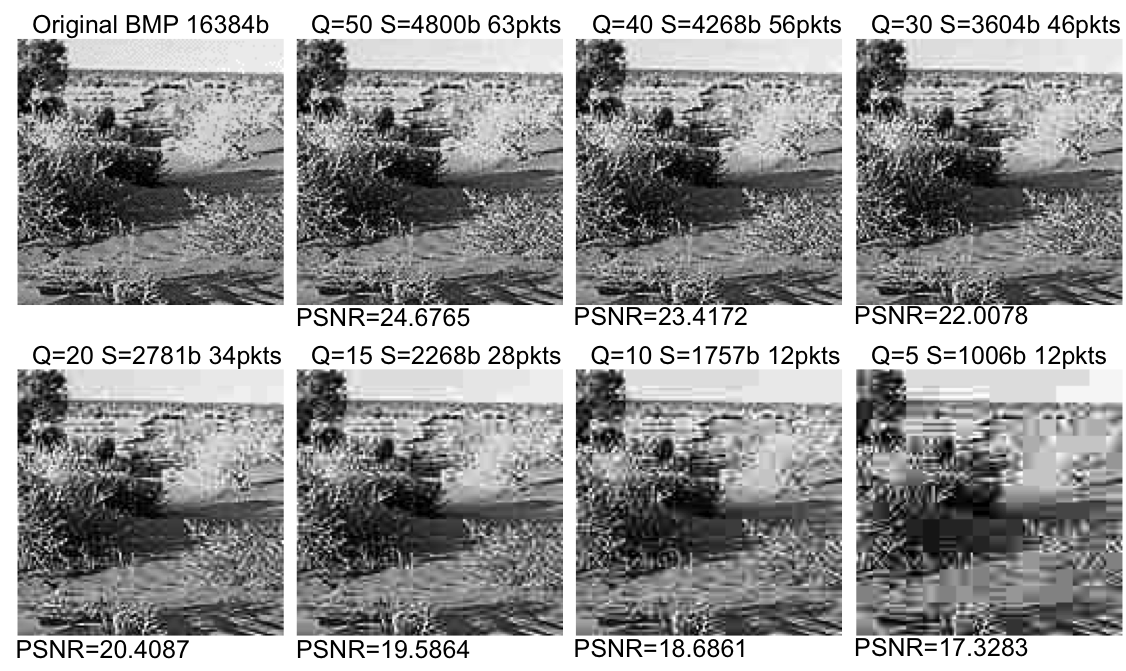
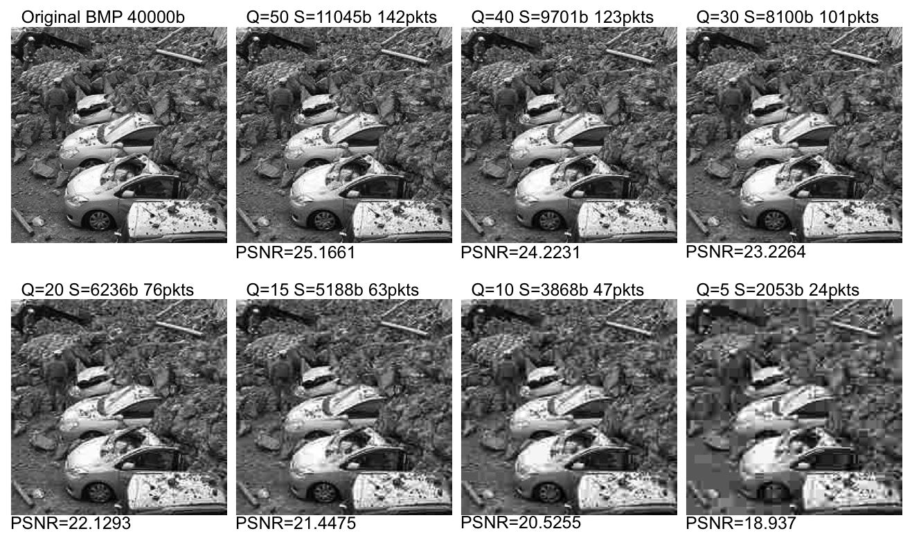
Figure below shows the impact of the Quality Factor for the
128x128 and 200x200 image. The image size and the number of
packets (max payload is set to 90 bytes) are specified. The PSNR
compared to the original .bmp image is also shown.
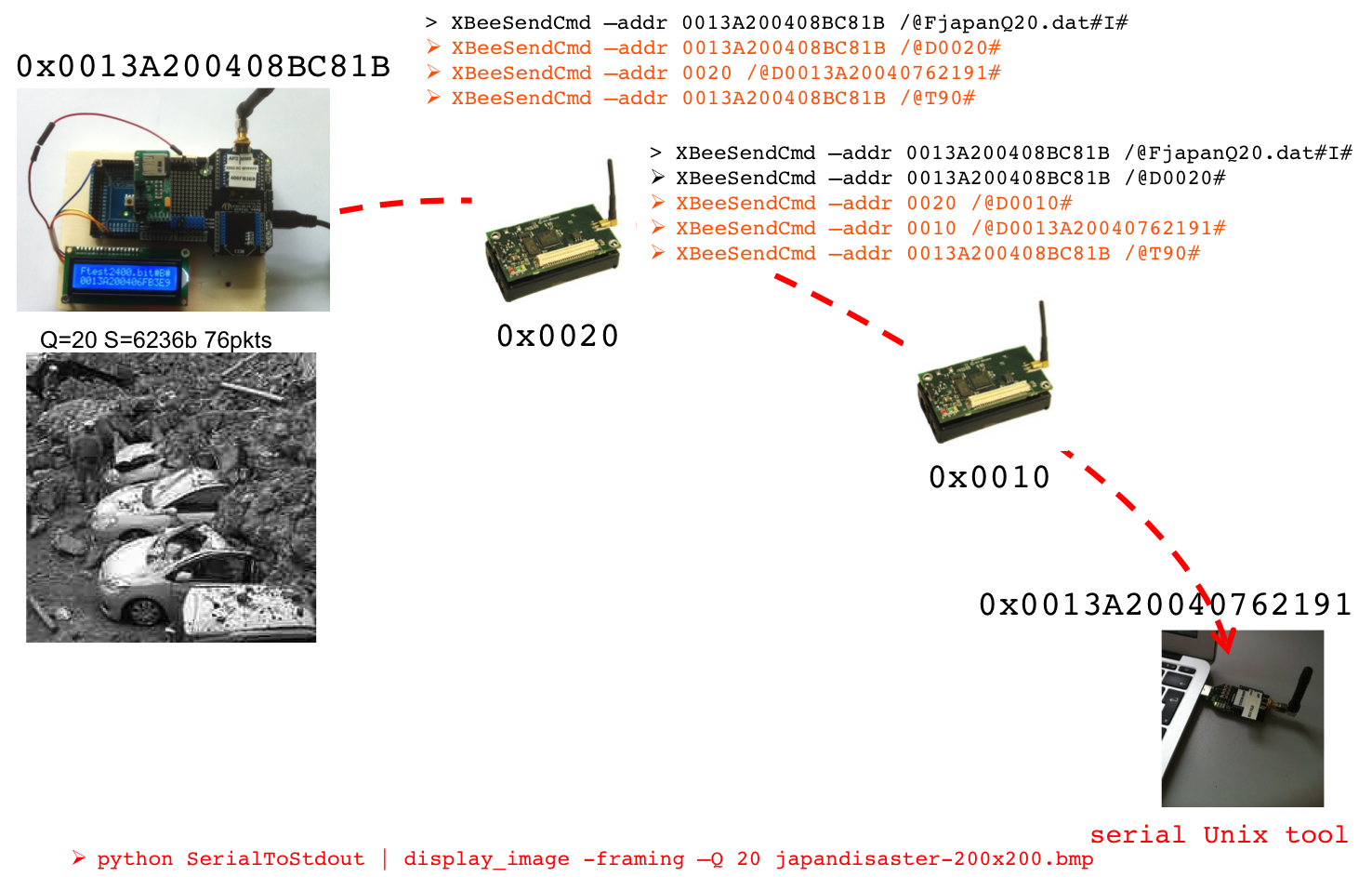
The script takes at least 4 parameters: the device port, the
initial command string for the source node, the source node and
the final destination node. A variable number of variable
intermediate nodes can be specified: in the example, nodes 0x0020,
0x0010 are intermediate nodes.
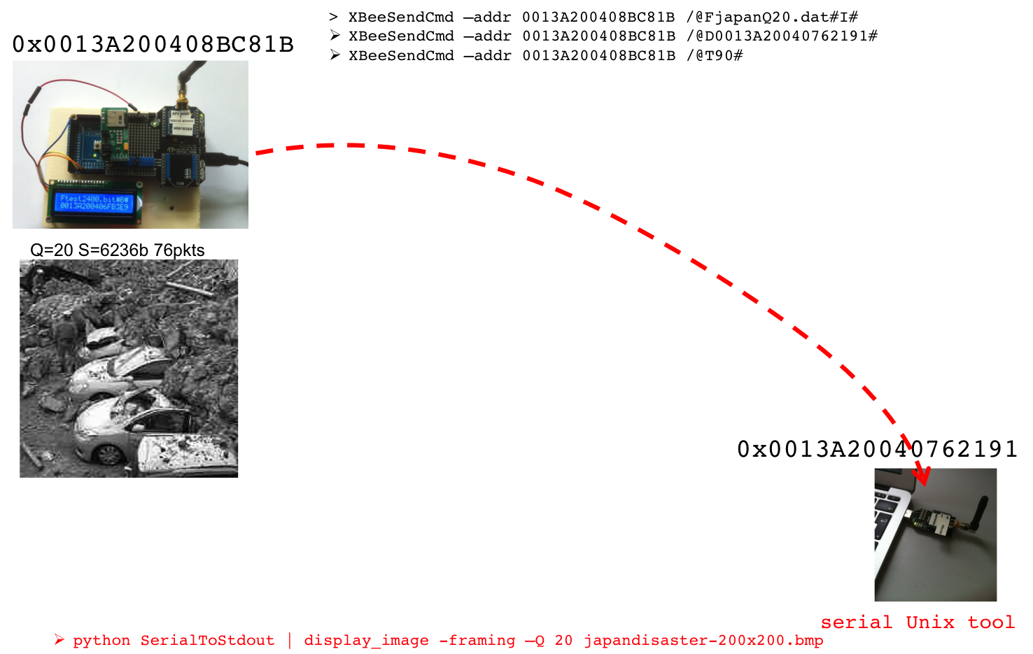
When the image transmission is triggered with command /@T90# sent
to the source node, the sink node should be ready to receive the
image packets.
--> PREFERRED
As specified previously, the display_image tool is used for that purpose.
As can be seen in the scenario, the simplest way to use this tool
is as follows:
> python 115200SerialToStdout.py
/dev/ttyUSB0 | ./display_image -timer 4 -framing -Q 20
japandisaster-200x200.bmp
If you use the TelosB BaseStation as a gateway, it communicates with the computer at 115200 (default speed of the TelosB). If you want to use an XBee USB gateway, you have to configure your XBee module with AP0 mode (ATAP0, transparent mode or so-called serial line replacement) and at the speed of 115200 (ATBD7) so that you can receive fast enough. We assume here that it is connected on /dev/ttyUSB0. -timer 4 indicates that the display timer is set to 4s, -framing indicates that packets have framing bytes as it is the default behavior of the sending node (only packets with framing bytes will be accepted), -Q specifies the Quality Factor, the one of the encoded image and japandisaster-200x200.bmp is the original .bmp file so that various information such as color palette could be obtained. This file should be accessible when you launch display_image. Here is an output example of display_image:
> python 115200SerialToStdout.py /dev/ttyUSB0 | ./display_image -timer 4 -framing -Q 20 japandisaster-200x200.bmp
set to framing mode
Wait for image, original BMP file is japandisaster-200x200.bmp, QualityFactor is 20
Display timer is 4s
Creating file tmp_1-japandisaster-200x200.bmp.Q20.dat for storing the received image data file
Wait for image
You can omit the -Q
option and make display take the one that is transmitted in
every packets in the framing bytes. This is particularly useful
when we use a real image sensor board with a camera where we can
define the Quality Factor for each image. See the "image sensor board built around an
Arduino Due and an uCamII" page.
<-- PREFERRED
--> OBSOLETE
As specified previously, the XBeeReceive tool can also be used for that
purpose. As can be seen in the scenario, the simplest way to use
this tool is as follows:
> XBeeReceive -I -framing -Q 20 japandisaster-200x200.bmp
-I indicates
the image mode, -framing
indicates that
packets have framing bytes as it is the default behavior of
the sending node (only packets with framing bytes will be
accepted), -Q specifies the Quality Factor, the
one of the encoded image and japandisaster-200x200.bmp is the original
.bmp file so that various information such as color palette could
be obtained. This file should be accessible when you launch XBeeReceive. Here
is an output example of XBeeReceive:
> ./XBeeReceive -I -framing -Q 20 japandisaster-200x200.bmp
set to framing mode
Serial Port open at: 3
Wait for image, original BMP file is japandisaster-200x200.bmp,
QualityFactor is 20
Creating file imageRcv.pktlist for storing
the list of received packets
Creating file tmp_1-japandisaster-200x200.bmp.Q20.dat
for storing the received image data file
Wait for image for 40s maximum
<-- OBSOLETE
When the display timer expires (you have to set the timer so that
all packets can be received, this time depends on the inter-packet
time you set for the source node), the receiver should display the
received image and wait for a key press. The received
packets are written in a file called tmp_1-japandisaster-200x200.bmp.Q20.dat
if the original BMP file is japandisaster-200x200.bmp and a .BMP version
of the received image will be stored in tmp_1-japandisaster-200x200.bmp.Q20.bmp
for immediate display (you can use any additional tool to
determine the impact on quality, such as the PSNR ratio, of the
received image compared to the original image). The image sequence
number will be increased for the next images but will be reseted
if you quit and run again the XBeeReceive program. By default the quality
factor is assumed to be 50 if you don't specify it. You should
make the receiver use the same quality factor than the sent
image.
As the File System on the SD card limits the file name to 8
characters plus the 3-character file extension, japanQ20.dat corresponds
to the japandisaster-200x200.bmp
image encoded at a Quality Factor of 50 (see above). You
can download all the image files (and audio file also but this
will be explained later on) in a .zip archive to put them
on your own SD card.The content is listed below:
desQ10.dat
desQ15.dat
desQ20.dat
desQ30.dat
desQ40.dat
desQ5.dat
desQ50.dat
japanQ10.dat
japanQ15.dat
japanQ20.dat
japanQ30.dat
japanQ40.dat
japanQ5.dat
japanQ50.dat
des*.dat
files correspond to the 128x128 image while japan*.dat correspond to the
200x200 images. We didn't use the 320x320 image.
IMPORTANT NOTE: the received packets are stored in tmp_1-japandisaster-200x200.bmp.Q20.dat.
But be careful, compared to the .dat file used to send the image,
the first 4 fields are not present so do not use the received file
for sending. Always send the file produced by the encoder
which format is:
XXXX: number of packets
XXXX: horizontal image size
XXXX: vertical image size
XXXX: quality factor
then XXXX XX XX .. .. XXXX XX XX ...
We can build a raw audio mote with a microphone connected to a
real sensor board such as Arduino. Need a program (.ino,
.zip) on
an Arduino to sample at 8Khz or 4KHz 8-bit/unsigned raw format
that send to a radio gateway (for instance an XBee module in AP
mode 0 configured at high baud rate, 125000 baud is needed for
8Khz sampling but 38400 is ok for 4000Hz sampling). You will also
need the TimerOne
library for Arduino. The original design for this experiment are
from P.Y. Lucas and E. Keita from the LabSTICC laboratory of U. of
Brest, under the supervision of Pr B. Pottier. Then use a python
script or another serial tool to read raw data received from
serial port. Here we use the 4kHz version and an XBee module
clocked at 38400 to have a standard baud rate:
> python 38400SerialToStdout.py
/dev/ttyUSB0 > test-raw.raw
> play --buffer 50 -t raw -r 4000 -u -1
test-raw.raw
If you use 8kHz sampling, the receiving XBee module must be
clocked at 115200:
> python 115200SerialToStdout.py
/dev/ttyUSB0 | play --buffer 50 -t raw -r 8000
-u -1 -
The sender XBee module must have DH and DL configure, either for
broadcast (DH=0x00000000, DL=0x0000FFFF) or to the address of the
receving XBee. Since the AP0 mode does not allow for dynamic
destination address confuguration, this has to be done prior to
transmission.
For 8kHz sampling, you need an XBee module at the sender side clocked at 125000. It is not possible to have 115200 baud rate (unless on the Libelium WaspMote version 2 board clocked at 14.75MHz) because of clock mistmatch between the microcontroller clock, both on Libelium WaspMote v1 (8MHz) and Arduino MEGA (16MHz), and the XBee clock.
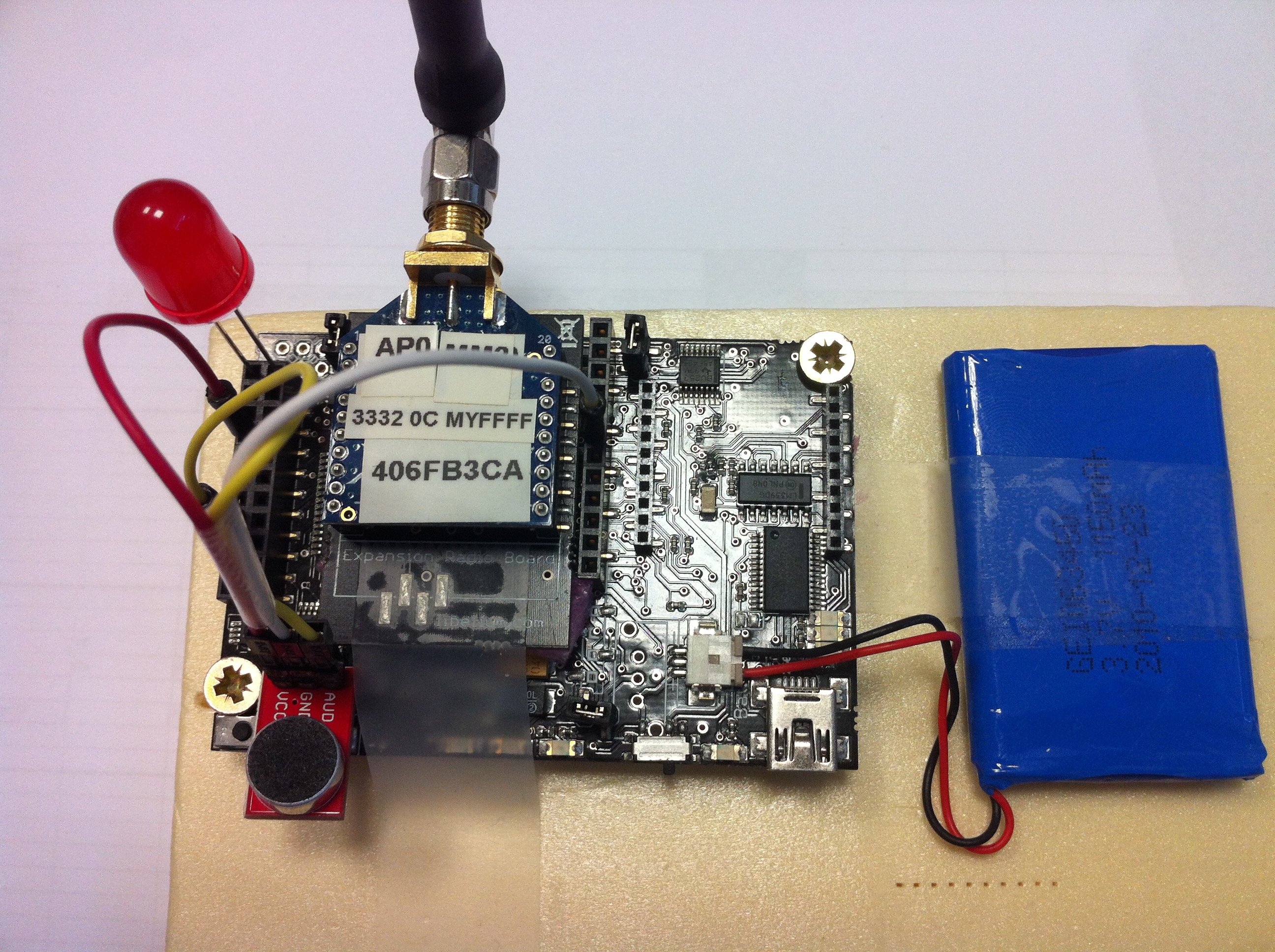
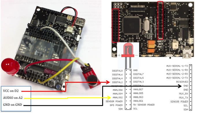
The left part of figure below shows our Arduino MEGA 2560 board
with the microphone (here
the one from CookingHacks) plugged into the analog 8 input pin.
GND and VCC 3.3v are taken from the corresponding pins. This is
the configuration used by the Arduino program. The right part of
the figure shows a more elaborated audio capture system as a led
indicates when capturing and streaming is on. We also have a more
elaborated program for Libelium WaspMote (that could be easily
ported to Arduino) that also show how to turn off the XBee module
to save energy when audio capture is off (.pde,
.zip).
As raw PCM audio is too bandwidth consuming for multi-hop audio,
we have to use a low bit rate audio encoding scheme. GSM codecs
are possible but we use some open-source codecs instead: codec2 and speex. Other formats are
possible of course. We describe below the steps for codec2 and
speex format.
The starting point is to have an audio file in raw format,
sampling rate of 8000Hz and 8-bit or 16-bit per sample, signed or
unsigned integer. There are various solutions:
We have a .raw sample file
(about 13s of audio in 16-bit) that you can listen in .wav format. Then we produced audio
files in various bit rate: 1400, 1600, 2400 and 3200. For the 2400
bit rate for instance, here is the .bit file, the associated .raw file and .wav file. You can get
the whole .zip archive
to test and play the files.
The .bit file are put on the SD card of the source node like in the image cenario. If you didn't already get it, here is a .zip archive containing the image files and the audio files to put on your own SD card. The content is added with the following audio files:
test1400.bit
test1600.bit
test2400.bit
test3200.bit
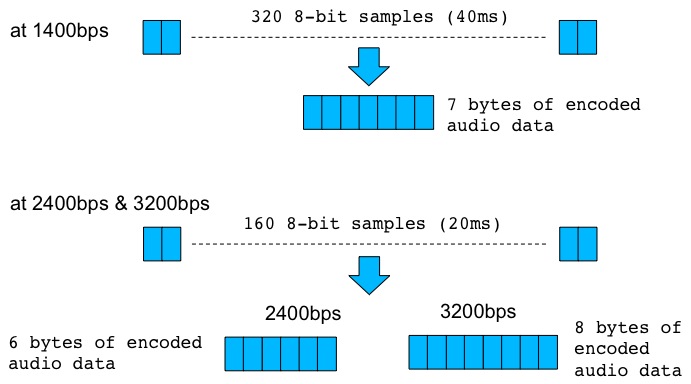
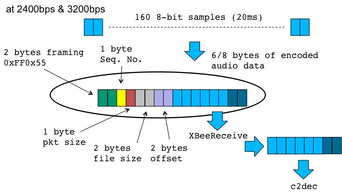
Depending on the bit rate, the audio frame size on codec2 is
different. Figure below shows how the codec2 encoder works.
Sending in binary mode
At the sender side, we defined the so-called binary sending mode
in which framing bytes (4 bytes) and reserved bytes (4 bytes) are
added to the real payload. To define binary mode, send "/@B#"
command to the source node. Figure below shows how from a real
payload of 6 bytes (codec2 2400bps), there are 8 bytes that are
added for the purpose of framing and reconstructing the file at
the receiver by handling missed packets or out-of-sequence
behavior.
Of course, you can specify a larger chunk size that would be
equivalent to perform aggregation at the source. For instance, if
you want to aggregate 2 audio frames to give a 12-byte payload,
then you can specify a chunksize of 12+4=16 bytes (the first 4
framing bytes are always added so they are not counted in the
chunksize). To aggregate 4 audio frames to give a 24-byte payload,
you can specify a chunksize of 24+4=28 bytes. Note that the pkt
size field stores the value of the chunk size.
Sending in so-called streaming mode
Example
You can notice the usage of the -B option to indicate to XBeeReceive that
data are in binary mode with reserved bytes to store the file size
and the offset in the file of each packet. Also, the -v 77 option
indicates that in case of packet losses, XBeeReceive must fill in missing
bytes with the hex value 0x77. This value has been empirically
found to provide little impact of the audio playout. At different
bit rate encoding, the adequate value may be different. You can
look at this page
which presents the results of the IEEE iThing 2013 paper (audio
tests on the SmartSantander test-bed). The figure below
illustrates this audio demo in which the bfr tool is used as an
intermediate buffer to c2dec for more control on the playout.
Summary and more details on XBeeReceive behavior
Given the previous test sample, we produced audio files in
various bit rate: 2150, 5950 and 8000. For the 5950 bit rate for
instance, here is the .spx
file, the associated .raw
file and .wav file.You
can get the whole .zip
archive to test and play the files encoded in speex at 2150, 5950
and 8000 bit rate.
Summary and more details on XBeeReceive behavior
display_image reads from standard input (stdin). You have to use a serial tool, or a python script for instance, to read from serial port and write back data on standard output. Use Unix pipe to inject data into display_image. The list of all options of display_image is shown below, can be obtained by running display_option without arguments:
USAGE:
./display_image -timer t -vflip
-onlydisplay/-onlydisplay_r img_file.dat -pgm/pgmb -pktd
-pktf -framing -Q q orig_image_file_name
USAGE: -timer 5, set display timer to 5s
USAGE: -vflip, flip vertically the received
image
USAGE: -onlydisplay img_file.dat, only display
the .dat file (produced by the encoder)
USAGE:
-onlydisplay_r img_file.dat, only display the .dat file
(previously received)
USAGE: -pgm/-pgmb, produce a PGM file
(ASCII) or binary
USAGE: -pktd, display received frames
USAGE: -pktf, generate pkt list file
USAGE: -framing, expects 0xFF 0x55-0x59 for
binary mode, 0xFF 0x50-0x54 for image mode, default is no
framing
USAGE: -Q 40, use 40 as Quality Factor,
default is 50
USAGE: orig_image_file_name, give the
original bmp file
-onlydisplay
is used to display an image encoded with the specific encoded
scheme from CRAN laboratory. The image must have been encoded
using the JPEGencoding
tool. If you want to re-display a transmitted image, use the
-onlydisplay_r
option. When displayed, the associated .BMP version of the image
will be created so that you can use this feature to get the .BMP
version of encoded images at various Quality Factor. Note that you
still have to mention the original .BMP file:
> display_image -onlydisplay desert-320x320-gray.bmp.M64-Q50-P302-S16595.dat
desert-320x320-gray.bmp
-pktd displays in hex format the received data
Note: the usage of XBeeReceive for image reception is now
OBSOLETE. Use instead display_image.
The list of all options of XBeeReceive is shown below, can be obtained by
running XBeeReceive
without arguments:
USAGE: ./XBeeReceive -baud b -p dev -onlydisplay img_file.dat -pktd -pktf -B/-I -framing -ap0 -v val –stdout -Q 40 file_name
USAGE: -baud, set baud rate, default is 38400
USAGE: -p /dev/ttyUSB1
USAGE: -onlydisplay img_file.dat, display the .dat file only
USAGE: -pktd, display received XBee frames
USAGE: -pktf, generate pkt list file
USAGE: -B/-I, -B for binary
mode, -I for image mode, default is image mode
USAGE: -framing, expects 0xFF0x55->0x59 for binary
mode, 0xFFx50->0x54 for image mode, default is no framing
USAGE: -ap0, indicates an Xbee in AP mode 0 (transparent mode) so do not decode frame structure
USAGE: -v 77, use 0x77 to fill in missing value in binary mode
USAGE: -stdout, write to stdout for pipe mode, don't work with image mode
USAGE: -Q 40, use 40 as Quality Factor, default is 50
USAGE: file_name, for
images: give the original bmp file. for binary: give any file
name
-onlydisplay
is used to display an image encoded with the specific encoded
scheme from CRAN laboratory. The image must have been encoded
using the JPEGencoding
tool. When displayed, the associated .BMP version of the image
will be created so that you can use this feature to get the .BMP
version of encoded images at various Quality Factor. Note that you
still have to mention the original .BMP file:
> XBeeReceive -onlydisplay desert-320x320-gray.bmp.M64-Q50-P302-S16595.dat
desert-320x320-gray.bmp
-pktd displays in hex format the received data
-pktf
generates in a file called imageRcv.pktlist or binRcv.pktlist (according to the
image or binary mode) the received packet for debugging purposes.
We also developped a simple program to send an image encoded with
the CRAN encoding scheme from a Linux-based machine with an XBee
USB gateway. You must have a USB/serial gateway to plug the XBee
module to the computer. display_image can be used at the other end
with another XBee module to receive the data. and display the
image. Remember that you must have the SDL library installed at
the receiver.
The list of all options of XBeeSendCRANImage is shown below, can be obtained by running XBeeSendCRANImage without arguments:
USAGE:
./XBeeSendCRANImage -baud baudrate -p dev -sensor -framing
-srcaddr a -camid id -Q q -L -timing pkt_us serialbyte_us
afterradio_us -nw -fake -drop d -pktd -pktf -mac|-net|-addr|-b
img_file
USAGE: -baud 125000, 38400 by default
USAGE: -sensor, will send image pkt to a
sensor for storage, need specific sensor behavior
USAGE: -framing, will use framing bytes
0xFF0x50+SN for image packets
USAGE: -srcaddr 1234, will use src addr
0x1234. Insert the src addr after the framing bytes 0xFF0x50
USAGE: -camid 1, set flow id to 1 to indicate
cam id 1 (0xFF0x51 are inserted)
USAGE: -Q 40, use 40 as Quality Factor,
default is 50.
USAGE: -L, insert Libelium API header
USAGE: -timing 50000 20 25000 by default
USAGE: -nw, do not wait for TX status response
USAGE: -fake, emulate sending. Will write in
fakeSend.dat, same format than original file (display with
display_image -onlydisplay fakeSend.dat original_bmp_file
USAGE: -drop 50, will introduce 50 of packet
drop. Useful with -fake
USAGE: -pktd, display generated XBee frames
USAGE: -pktf, generate a pkt list file
USAGE: -mac 0013a2004069165d
USAGE: -net 5678
USAGE: -addr 64_or_16_bit_addr, set either
64-bit or 16-bit dest. address
USAGE: -b, for broadcast
USAGE: img_file, image .dat file with CRAN
encoding
XBeeSendCRANImage (get the .c file) can be compiled as follows:
> g++ -gstabs+3 -Wno-write-strings -o XBeeSendCRANImage
XBeeSendCRANImage.c -lrt -lm
At the sender side you can use XBeeSendCRANImage in the following
way:
> XBeeSendCRANImage -b
desert-320x320-gray.bmp.M64-Q50-P302-S16595.dat
-b will use broadcast. You can use 64-bit or 16-bit destination
address as follows:
> XBeeSendCRANImage -mac 0013A20040675645
desert-320x320-gray.bmp.M64-Q50-P302-S16595.dat
> XBeeSendCRANImage -net 1234
desert-320x320-gray.bmp.M64-Q50-P302-S16595.dat
At the receiving side, you must launch the XBeeReceive first with:
> XBeeReceive -I desert-320x320-gray.bmp
by mentioning the name of the original BMP file. Then launch the
sender and you should see packets that are received. When all
packets have been received, the receiver should display the
received image.
At the sending side, there are advanced options for the serial
port that can change the transmission time of the image. However,
be careful when playing with these advanced parameters. There are
3 delays that are important when transmitting a continuous flow of
packets on the serial port for the XBee module (the XBee should be
in API mode 2):
By default these delays are respectively: 50000us 20us and
25000us. You can change them when sending an image:
> XBeeSendCRANImage -timing 40000 30 20000 -b
desert-320x320-gray.bmp.M64-Q50-P302-S16595.dat
will set (1) the time between 2 packet send to 40000us (40ms), (2)
the time between 2 write on the serial port for the radio to 30us
and (3) the time to wait after having send a packet to a radio
module before waiting for the TX status request to 20000us (20ms).
Do no set (1) too small, 40ms is quite fast for these kind of
hardware because since there are no flow control at the receiving
side, receiving buffer could be easily overflown. (2) should be
left at the this default value of 20us, it does not change
dramatically the transmission time. (3) could be set smaller but
you may not get the TX status response. However, not getting the
response in time does not mean that your packet has not been sent.
Therefore, you can save time here by additionally disabling the
wait for an answer with the -nw (no wait) parameter:
> XBeeSendCRANImage -timing 40000 30 100 -nw -b
desert-320x320-gray.bmp.M64-Q50-P302-S16595.dat
See that with the -nw
parameter we do not wait for the answer, so there is no reason to
set (3) at a high value (here we reduce to 100us) since (1) will
regulate the time between 2 packet send. With the -timing
parameter, you MUST indicate all 3 values, even if you want to
use the default values.
XBeeSendCRANImage
can also emulate the sending by writing in a file the image
packets, just like they have been sent. The file have the same
structure than the input file to be displayed directly with XBeeReceive/display_image.
To do so, just add -pktf
-fake in your usual command:
> XBeeSendCRANImage -pktf -fake -b
japandisaster-200x200.bmp.M90-Q50-P142-S11045.dat
It will produce a fakeSend.dat
file that is normally exactly the original .dat file. This feature
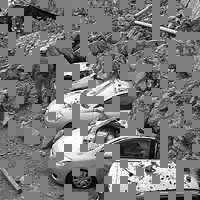
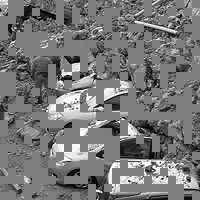
is interesting when combined with the -drop parameter that specifies a
packet drop rate:
> XBeeSendCRANImage -pktf -fake -drop 50 -b
japandisaster-200x200.bmp.M90-Q50-P142-S11045.dat
You can then display the image and see what is the impact of
packet losses on the quality, the advantage is that you can
control the packet loss rate:
> display_image -onlydisplay fakeSend.dat
japandisaster-200x200.bmp
display_image
will then display the image and produce the associated .BMP file (tmp_1-japandisaster-200x200.bmp.Q50.bmp)
that could just be renamed into tmp_1-japandisaster-200x200.bmp.Q50-50dropped.bmp
for instance.
Note that the usage of -Q is now obsolete as the original quality factor is coded in the image file. In this way, the decoder can always have the correct quality factor used to encode the source image.